
Instruction Manual


D
GB
F
E
19
96098-11.2014-DGbFE
5| Electrical connection
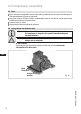
5.6 External connection of the MP 10 for terminal boxes at reduced height (Accessories)
Terminal box
PTC1
PTC2
1
2
3
4
3
4
PE
R2
ThecompressorandthetriggerunitMP10areoperationalwhentheH3LED(green)illuminates.
X3:
5.7 Function test of the trigger unit MP 10
Item
Procedure
LED H1 LED H2 LED H3
Red Red Green
1
• Power supply interrupted (L1 or S1) OFF OFF OFF
• Releasethemotortemperaturesensorconnection(1or2)
• Releasethehotgastemperaturesensor(ifinstalled)(3or4)
2
• Restore the power supply (L1 or S1) ON
• Functioncheckofmotortemperaturesensor:operational ON
• Functioncheckofhotgastemperaturesensor:operational ON
3
• Power supply interrupted again (L1 or S1) OFF OFF OFF
• Reconnect terminals 1 or 2 and/or 3 or 4
4
• Restorethepowersupply(L1orS1): OFF OFF ON
• MP 10 is operational again
Before start-up, troubleshooting or making changes to the control power circuit,
checkthefunctionalityofthetriggerunit:
Fig. 23
0.5 mm²