
Instruction Manual


16
D
GB
F
E
96098-11.2014-DGbFE
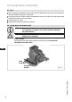
R1 Cold conductor PTC sensor motor winding
R2 Thermalprotectionthermostat(PTCsensor)
F1 Load circuit safety switches
F2 Control power circuit fuse
F3 Safetychain(high/lowpressuremonitoring)
B1 Releaseswitch(thermostat/pressostat)
Q1 Main switch
5.3 Circuit diagram for direct start 230 V ∆ / 400 V Y
Fig. 21
Terminal box compressor