
Technical Specifications

ValVue Digital Communications Software Ver. 2.80
542
GE Oil & Gas
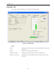
Calibration Parameters Tab
See “Monitor Tab” on page 527 for nameplate data configuration.
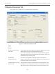
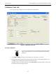
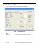
Figure 5 Calibration Parameters Tab
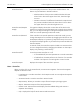
Fields
Ranges
Low level, High Level and
Level units
The low and high values of liquid level and the engineering units that
appear when the tank is respectively empty and full.
The low and high values of the interface and the engineering units
that appear when the tank is filled with the low specific gravity and
filled with the high specific gravity.
Zero Shift (%) The value in percentage of calibration scale to shift the zero.
Damping (seconds) Output current filtering. The value is expressed in seconds and corre-
sponds to T63% for a first order filter.
Low Current (mA) and High
Current (mA)
The signal that is sent by the transmitter corresponding to the low
and high level or interface level for direct transmitter action or the
high and low level or interface level for reverse transmitter action.