
Technical Specifications


ValVue Digital Communications Software Ver. 2.80
278
GE Oil & Gas
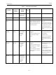
The maximum voltage that can be applied to the digital switch outputs is 30 VDC. This is an
open circuit parameter (the digital switch is in the open state). Under open circuit conditions,
the switch current will be less than 0.200 mA.
The switch maximum current rating is 1 A. When the switch is ON, the typical voltage drop
across the switch is V. It is essential that the external circuit controls voltage such that the
switch saturation voltage is maintained.
When the switch is on (closed) the external voltage must be dropped across the load
(Figure 68).
CAUTION The load must be designed such that the current in the circuit is
1 A at all times. Some 3rd party devices, such as incandescent
lamps or solenoids, require surge and back EMI protection to limit
current to
1 A.
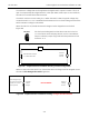
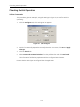
Figure 68 Simplified Switch Installation Drawing: Correct Configuration
Without a load, when the switch is on (closed) the external voltage would be dropped across
the switch. This damages the switch (Figure 69).
Figure 69 Simplified Switch Installation Drawing: Configuration Not Allowed
SVi1000 Switch Output:
1 V with switch ON
External
Voltage
Source
LOAD
Load is designed to ensure that voltage across the switch is < 1 V.
SVi1000
Switch
Output
External
Voltage
Source
NOT ALLOWED
Full voltage drop is
occurring across the
switch (no current
limit in place)