
Technical Specifications


115
Custom Linearization
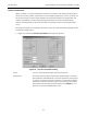
Configure Screen
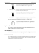
Compound Lever The compound lever linkage has two lever segments attached at
one end to the pivot and the other end to the valve stem pickup
point. In order to compute the proper correction curve, you must
enter the stroke length, first lever segment length (L1), second lever
segment length (L2), the distance from the pivot to the valve stem
pickup (L3), the valve position at horizontal. Click Compound to
compute the correction and display the curve.
Most Masoneilan linkages use a linkage with L3 equal to L1, i.e. the
second lever arm is vertical when the first lever arm is horizontal.
The correction computation correctly computes the correction
curve when L3 is not equal to L1, however L3 must be greater than
0 which requires that the valve stem pickup not be lined up with
the pivot and that the pickup be on the same side of the pivot as
the link between the first and second lever segments.
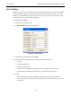
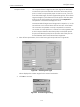
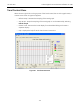
2. Enter all lever parameters, click on the lever type (Compound lever in Figure 85).
Figure 85 Selecting Lever Type
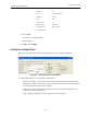
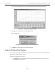
ValVue displays the rotation angle for the custom linearization.
3. Click OK to continue.
Figure 86 Rotation Angle Dialog