
Technical Specifications


ValVue Digital Communications Software Ver. 2.80
114
GE Oil & Gas
Custom Linearization
When mounted on a reciprocating valve, a small non-linearity in the reported valve position
versus actual valve position may result from the linkage configuration. This non-linearity can
be corrected using a custom characterization that matches the specific linkage used. The
custom linearization procedure automatically generates this custom characterization.
Custom characterization must be the selected configuration option to use the generated
curve.
Two types of linkages are modeled: simple and compound. Most Masoneilan linkages use the
compound linkage system.
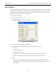
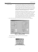
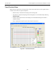
1. Right-click and select Custom Linearization and Figure 84 appears.
Figure 84 Custom Linearization Dialog
Levers You can customize both simple and compound lever.
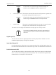
Simple Lever The simple lever has the pivot point (the potentiometer in the SVI II
AP) mounted a fixed distance (L1) from the valve stem pickup point.
In order to compute the proper correction curve, the stroke length,
the distance from the pivot to the valve stem pickup point and the
valve position at horizontal must be entered. Click Simple to com-
pute the correction and displays the curve.