
Technical Specifications

ValVue Digital Communications Software Ver. 2.80
110
GE Oil & Gas
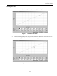
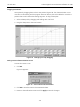
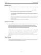
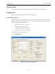
The I/O Configure window appears (Figure 81).
2. Adjust the parameters and click OK to save changes and return to the Configure screen.
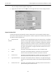
Figure 81 I/O Configure Window
Output Switches (DO)
The SVI II AP supports two identical contact outputs which can be logically linked to status
bits. The two output switches can be opened or closed in response to conditions that the SVI II
AP detects. These conditions are:
0. Always Normal
Position
The switch is not controlled by the SVI II AP and remains in it’s default
position. The two digital output switches can be opened or closed in
response to detected conditions. The default configuration setting is
Always Normal Position, where normal is closed, which means that
the switch will not switch for any valve travel. To activate the switch
at a given valve position, configure the switch Position Low Limit or
Position High Limit.
1. Failsafe The switch is activated when the SVI II AP is in failsafe mode.
2. Reset The switch is activated whenever a reset has occurred and the
switch remains activated until the SVI II AP status is cleared.
3. Position Error The switch is activated whenever a position error has occurred and is
deactivated when the position recovers to the correct position.
4. Tight Shutoff Active The switch is activated whenever the device is in tight shutoff (tight
shutoff is on and the valve position is less than the tight shutoff posi-
tion).
5. Position Low Limit The switch is activated whenever the valve position is less than the
position setting of this switch control.