
Technical Specifications


ValVue Digital Communications Software Ver. 2.80
100
GE Oil & Gas
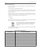
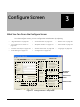
NOTE ValVue must be in Setup mode to make any configuration changes
on this screen.
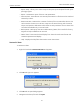
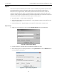
Tag Information
The Tag information contains an extra field, Polling Address. To change Tag information:
1. Enter data.
2. Click Apply.
Polling Address
The Polling Address doesn’t appear in the Tag information on the Monitor screen.
HART can communicate with up to 64 devices on a single pair of wires. These devices are
distinguished by their polling address which number from 0 to 63. If there is a device at polling
address 0, it must be the only device on the loop. There can be up to 63 devices with non-zero
polling addresses on the loop (subject to power and intrinsic safety constraints). For an SVI II
AP HART 6 device, polling address can be up to 63. Devices which operate 4-20 mA are
generally required to have polling address 0, however with split range valve positioners,
several 4-20 mA devices can be wired in series. Set these devices up with non-zero polling
addresses.
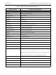
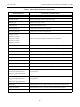
Table 6 Polling Address Applications
Positioner Application Polling Address Comment
Normal default on current loop 0 Use this for all single loop control.
Split range on a single current
loop
1 to 63 Give each device on the current loop a
unique address. 0 can cause errors. Use
the Options dialog to specify particular
addresses or an address range to save
scanning time.
Split range with each positioner
on a current loop powered by iso-
lator
1 to 63 Give each device operated by a single
controller a unique address. 0 can cause
errors. Use the Options dialog to specify
particular addresses or an address
range to save scanning time.
Multidrop in voltage mode 1 to 63 Used with HART multiplexor. Follow
instructions of Mux manufacturer.