
Technical Specifications


43
Active Faceplate
Using ValVueFF
Active Faceplate
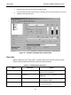
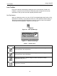
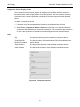
Figure 38 shows an active Positioner Faceplate frame with complete functionality:
❑ The control valve tag is shown in the PD-Tag field.
❑ The current operating state of the positioner is shown in the Operation field. In
this example the display reads, NORMAL STATE.
❑ Block Mode Actual displays individual block modes appear for each of the
positioners internal function blocks.
❑ The valve position Set Point appears next to the graphical position of a slider
control, numerically to two decimal places.
❑ Below the Set Point display, the target position and actual position are shown as
a slider and bar, respectively, with values shown to two decimal places.
The Target Position is obtained from the Set Point signal using parameters defined
using Configure (see page 79), from valve characterization and the configuration of
air-to-open or air-to-close, also defined in Configure. It is further modified by any
configured limits. In Figure 38 the incoming setpoint and the target position differ as an
equal percent characteristic is used. If a linear characteristic and air-to-open are
configured, with limits configured outside the possible range of position, the Target
Position is equal to the Set Point.
Figure 38 IVI Faceeplate in Normal State