
Technical Specifications
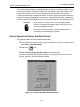

ValVueFF Software Interface to FVP
216
GE Energy
ValVueFF manages the operational states of the positioner and its embedded PID
controller by controlling the target modes for each of the function blocks. The actual mode
of each block can be different from the target mode. The actual mode is controlled by the
block itself in accordance with mode rules based on the quality of the data and modes of
the linked blocks. A brief summary of modes follows, a thorough discussion of modes is
beyond the scope of this instruction manual. You can refer to the Fieldbus Foundation
that specifies the formal rules for mode changing.
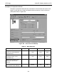
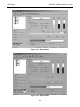
Three operational states are set by ValVueFF (Figure 179) Out Of Service (OOS) Forces
all of the blocks to Out Of Service Mode. The outputs remain at the values prior to the
state change. All output calculation is suspended. Back calculation values are passed to
other linked blocks to enable initialization. The PID block remains in OOS after
configuration changes unless it is put into one of its allowed modes from the PID dialog
box. The PID dialog box can be started from the Device Operation Dialog box.
Block Modes
All blocks (function/transducer/resource) have operating modes. There are eight modes
defined in the Foundation Fieldbus specification. Not all modes are supported by every
block. For example, the Discrete Input Block (DI) supports Auto, Man and OOS. The
action of the modes are described in the following paragraphs. Transfers between modes
are managed by the function blocks in response to manual commands that in turn
responded to changes in the modes of linked blocks and responded to changes in the
quality of the parameters that are transmitted. Control and status options can be set to
manage mode changing behavior.
Remote-Output
(Rout)
The block output is set by a control application running on an
interface device through the remote-output-in parameter. The
algorithm is bypassed and the remote block controls its output
directly. The algorithm must initialize so that no bump is experi-
enced when the mode switches to Auto. A remote-output-out
parameter is maintained by the block to support initialization of
the control application when the block mode is not remote- out-
put. The Set Point can be maintained or initialized to the process
variable value.
Remote-Cascade
(RCas)
The block Set Point is set by a control application running on an
interface device through the remote-cascade in parameter. Based
on this Set Point the normal block algorithm determines the pri-
mary output value. A remote-cascade out parameter is main-
tained by the block to support initialization of the control
application when the block mode is not remote-cascade.
Cascade (Cas) A Set Point value supplied by another function block through the
Cascade input parameter is used by the normal block algorithm in
determining the primary output value. This connection between
function blocks is defined by a link object.