
Technical Specifications

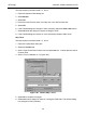
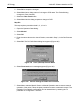


ValVueFF Software Interface to FVP
184
GE Energy
CAS Cascade mode A string must be typed exactly in upper-case (capital) letters and
lower case. For example Admin is the correct username of the
ValVueFF administrator, but admin is rejected at logon.
Characteristic The positioner input setpoint command can be selectively modi-
fied to provide a desired relationship between setpoint and valve
position. In the valve, the relationship between stroke and Cv is
also called valve inherent characteristic. It is often adjusted by
design, to equal percentage, for example. The positioner charac-
teristic is applied to modify the setpoint to travel relationship of
the actuator. Choose the characteristic of the positioner to compli-
ment the valve. If the valve is equal percentage, set the positioner
to linear. If a linear valve is installed the positioner can be set to
an equal percentage characteristic to improve flow control. FVP
offers an eleven point custom characteristic option which can be
easily created and edited in ValVueFF. Use local display to select
the custom characteristic, but you cannot adjust the points.
Closed The valve position in which the flow is minimum or zero. See tight
shutoff.
Communications
Stack
This is device communications software that provides encoding
and decoding of User Layer messages, deterministic control of
message transmission, and message transfer.
Compliance Voltage The voltage that must be available at the control system output in
order to drive the control current through the FVP and all the
resistive devices in series with it.
Compliance, HART Manufactured and tested in accordance with the HART Commu-
nications Foundation standards.
Condition Monitoring A technology for measuring the performance of process equip-
ment and valves over a period of time to predict the need for
maintenance. The technology evolved to meet NRC requirements
GL 89-10, and has proven valuable to other process industries.
FVP and ValVueFF offer a suite of diagnostic tools to implement
condition monitoring.
Connector This is a coupling device used to connect the wire medium to a
fieldbus device or to another segment of wire.
Control Loop This is a group of Function Blocks (FBs) that execute at a speci-
fied rate within a fieldbus device or distributed across the fieldbus
network.
Coupler This is a physical interface between a Trunk and Spur, or a Trunk
and a device.
D Derivative time or rate time is the time constant of derivative con-
trol expressed in seconds. A value of zero disables derivative
action.