
Technical Specifications


85
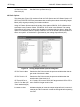
Limit Switch Threshold
Configuration Services
Limit Testing
1. Isolate the valve from the process.
2. Place the FVP in Manual Operating State. The valve must be calibrated and
supplied with correct supply pressure.
3. Measure closed position by:
a. Entering a Set Point of -10%.
b. Wait for the valve to reach it's final value and record the actual position of the
closed mechanical stop. The actual position must be less negative than the
target position to verify the valve has reached the stop. If the actual position and
target position are equal, reduce the Set Point until the valve reaches the stop.
4. Disable Tight Shutoff Below and Position Lower Limit by deducting 10% from the
recorded value.
5. Measure open position by:
a. Entering a Set Point of 110%.
b. Wait for the valve to reach it's final value and record the actual position of the
open mechanical stop. The actual position must be less than the target position
to verify the valve has reached the stop. If the actual position and target position
are equal increase the Set Point until the valve reaches the stop.
6. To disable Full Open Above and Position Upper Limit add 10% to the value
recorded above.
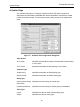
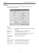
Limit Switch Threshold
The Limit Switch thresholds apply to the Discrete Input Block (DI) Set Points.
Threshold Low Threshold for the low limit switch that communicates by the DI.
Threshold High Threshold for the high limit switch that is communicated by the
DI.
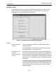
Fault Control
Error Band The position deviation limit to start Time 1 deviation timer and
Time 2. Set this value to a value that is exceeded only in abnor-
mal performance.
Time 1 The position deviation time limit to show the block alarm. A neg-
ative value turns off this function. Set this value greater than the
stroking time.
Time 2 The position deviation time limit to trigger the failsafe action. A
negative value turns off this function.