
Technical Specifications


© 2014 General Electric Company. All rights reserved.
94 | =GE Oil & Gas
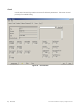
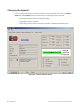
PST Controller Characteristics
The PST controller Characteristics displayed on the Monitor screen consist of:
Signal (mA) - Indicates the input analog signal expressed in mA.
Position (%) - Indicates the actual valve position in % of valve opening. 0% is always
closed and 100% is open.
Pressure (pressure units) - The SVI II ESD continuously monitors the actuator pressure.
It is displayed according to the configured units (psi, bar, or kpa).
I/P Current - the current in mA generated by the I/P.
Pressure1 (pressure units) - Actuator pressure when Single Acting.
Pressure2 (pressure units) - Has no value when Single Acting.
Supply (pressure units) - Pressure generated by the air supply.
Pilot Pres (pressure units) - pressure generated by the I/P.
Pressure, Pressure1 and Pressure2
If your unit is single acting, Pressure and Pressure1 both have the same value, the actuator
pressure.
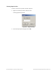
Position Indicator
The Position Indicator shows the valve position graphically. The indicator consists of three
parts:
The upper part contains an indicator showing the value of the input signal. In Normal
mode this is the position setpoint.
WARNING If operating in manual mode, this is the position that the valve
moves to if returning operation to normal mode.
The center green bar shows the valve position where % = Valve Open. The numerical
valve position is shown in the center.
The lower part contains an indicator (thumb) showing the valve setpoint. In operating
mode, this is the same as the signal. In manual mode it is the valve setpoint. You can
drag the thumb to change the valve setpoint. While dragging, the number in the center
bar shows the manual setpoint for use when you release the thumb.
Signal
Indicates the input analog signal expressed in % of the configured signal range.