
Technical Specifications


© 2014 General Electric Company. All rights reserved.
132 | =GE Oil & Gas
The maximum voltage that can be applied to the digital switch outputs is 30 VDC. This is an
open circuit parameter (the digital switch is in the open state). Under open circuit conditions,
the switch current will be less than 0.200 mA.
The switch maximum current rating is 1 A. When the switch is ON, the typical switch voltage is
V. It is essential that the external circuit controls voltage such that the switch saturation
voltage is maintained.
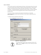
When the switch is on (closed) the external voltage must be dropped across the load
(Figure 109).
CAUTION The load must be designed such that the current in the circuit is
1 A at all times. Some 3rd party devices, such as incandescent
lamps or solenoids, require surge and back EMI protection to limit
current to
1 A.
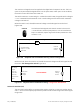
Figure 109 Simplified Switch Installation Drawing: Correct Configuration
Without a load, when the switch is on (closed) the external voltage would be dropped across
the switch. This damages the switch (Figure 110).
Figure 110 Simplified Switch Installation Drawing: Configuration Not Allowed
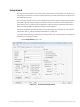
Position Transmitter (AO)
The SVI II ESD has the ability to retransmit the position signal as an output to another device
with 4 - 20 mA current output proportional to position. Enter a lower range value and an upper
range value.
SVI II ESD Switch
Output: 1 V with
switch ON
External
Voltage
Source
LOAD
Load is designed to ensure that voltage across the switch is < 1 V.
SVI II ESD
Switch
Output
External
Voltage
Source
NOT ALLOWED
Full voltage
drop is
occurring
across the
switch (no
current limit in
place)