
Brochure


17
Unit Size
A*
inches (mm)
B*
inches (mm)
C**
inches (mm)
D
inches (mm)
E
inches (mm)
Weight
lbs (kgs)
HN
18 (450) 14 (350) 192 (4880) 72 (1830) 78 (1980) 35,000 (15,875)
HP
30 (750) 24 (600) 220 (5600) 102 (2590) 98 (2490) 71,500 (32,430)
HQ
36 (900) 24 (600) 240 (6100) 108 (2740) 120 (3050) 78,000 (35,380)
HR
42 (1050) 24 (600) 250 (6350) 120 (3050) 132 (3350) 92,000 (41,730)
HT
48 (1200) 36 (900) 260 (6600) 138 (3500) 150 (3810) 130,000 (58,970)
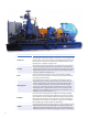
Roots Type H Multi-Stage Dimensional Table
*Flanges are rated at 25# (Typ.) and drilled per ANSI B16.5 & B16.47A
**Total length is subject to change based on number of stages or the need for a gear box
NOTE: Inlet and Discharge of Compressor may be oriented in either the top or bottom direction, or any combination of the two.
NOTE: Compressor may be driven through Inlet or Discharge End.
A
E
B
INLET
DISCHARGE
D
C