
Technical Specifications


63
Tri-Loop Configuration
Advanced Setup with ValVue
Tri-Loop Configuration
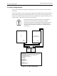
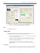
Figure 44 is a simplified schematic showing the SVI II and Tri-Loop and a control system
connection
The input channel from the control system must have an impedance of at least 250 Ohms or
else the HART signal becomes attenuated and the Tri-Loop won’t function properly. Also,
channel one must be enabled and set for Primary Variable with a range of 0-100%. You can
enable channel 2 and 3 even if you don’t connect them.
NOTE Consult the TRI-LOOP instruction manual for wring diagrams.
Masoneilan is not responsible for improperly wiring the
TRI-LOOP. This document simplifies the setup requirement of an
SVI II with a device such as a TRI-LOOP. A resistor might be
required on the positive leg of Channel 1 to limit the current to
the TRI-LOOP.
Figure 44 Tri-Loop Configuration
TRI-LOOP
MODEL 333d or 333u
Ch 3 Ch 2 Ch 1
- + - + - +
Comm Burst Input
- + - +
SVI II
+ -
Loop
Power
4-20mA
Analog
Output
Analog
Input
+ -
+ -
24Vdc
SVI II Configuration:
HART Address = 0
Set BURST MODE to HART cmd#3 (with ValVue) or PROCESS-
VARS CURRENT (with Handheld or DD enabled Host)
PV is Valve Position (0-100%)
SV is Actuator Pressure (0-120 psi)
TV = Not Used
QV= Not Used
TRI-LOOP Setup
HART address =1
CHANNEL = ENABLE
Variable = PV
Upper Range Value = 100
Lower Range Value = 0
Units: %
250ohm