
Technical Specifications

607
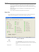
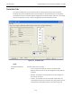
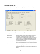
Controller Tab
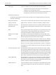
Controller Status The alarm status indicates when the process variable is outside of
the user specified range of upper alarm limit and lower alarm limit.
The alarm can be specified as an absolute range or as a deviation
from setpoint.
Setpoint Indicator The graphical display shows the process variable (bar) and the pro-
cess setpoint (thumb). The process variable is measured from the
2nd input signal (auxiliary input signal) and scaled to engineering
units.
In remote mode, the process setpoint is measure from the
primary input signal and scaled to engineering units.
In local mode, the setpoint is set by the user and may be
changed by dragging the thumb or by right-clicking on the
thumb and typing a value.
In manual mode, the setpoint is ignored.
Remote Setpoint The process controller setpoint is measured at the primary input
sensor and is scaled in engineering units according to the data
entered on the calibration tab. If ratio control is selected, the set-
point units may be different from the process variable. The remote
setpoint field shows the remote setpoint even when the controller
is in local mode or manual mode.
Scaled Setpoint When ratio control is selected, the remote setpoint is linearly
scaled by user input parameters to calculate the scaled setpoint
for use by the process controller. The scaling can be used to
change to setpoint engineering units to match the process vari-
able.
Setpoint The setpoint of the process controller. When ratio control is
selected, this is the scaled value in the same units as the process
variable. In local setpoint mode, the setpoint can be changed by
dragging the thumb in the process setpoint indicator or by
right-clicking on the indicator and typing a value.
Process Variable The process variable is the value in engineering units of the pro-
cess being controlled and measured from the transmitter signal
attached to the 2nd signal input (auxiliary signal).
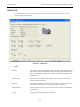
Controller Output When the controller is on, this value is the signal in percent sent to
the positioner from the process controller.
Controller Output Indicator The graphical display shows the output of the process controller
from 0% to 100% and the valve position (uncharacterized to match
the controller output). In manual mode, the thumb can be dragged
to change the valve position.