
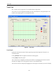
Technical Specifications

537
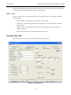
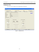
Configuration Tab
Fields
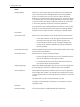
Polling Address HART can communicate with up to 15 devices on a single pair of
wires. These devices are distinguished by their polling address,
which is a number from 0 to 15. If there is a device at polling
address 0, it must be the only device on the loop. There may be up
to 15 devices with non-zero polling addresses on the loop (subject
to power and intrinsic safety constraints). Devices which operate
4-20 mA are generally required to have polling address 0.
Any transmitter with a polling address set between 1 and 15 have
their the current output fixed to 4mA.Never set a polling address
between 1 and 15 when the HDLT is working in controller mode.
Transmitter
Transmitter Mode Allows you to select either level or liquid interface measurement:
In the level indicator mode, the signal indicates the level of
the liquid in the tank of a known specific gravity fluid.
In the interface indicator mode, the signal indicates the
position of the interface between two liquids of different
specific gravities.
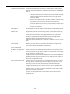
Transmitter Mounting Selects whether the HDLT head is mounted at the left or at the right
position versus the displacer.
Transmitter Action Selects direct or reverse acting transmitter:
In direct acting transmitter, the current increases when the
level or the interface of the liquid increases.
In reverse acting, the current decreases when the level or
the interface of the liquid decreases.
Display Language Selects the display language of the HDLT as French or English. Only
the LCD display on the HDLT is affected (not the PC software).
Lock Out Buttons When selected this option prohibits access to manual, calibration
and configuration modes. You need to enter a password (for HDLT
revisions greater than 4.12) through the push buttons to access all
modes.
The password must be a number between 1 to 255.
The HDLT is automatically locked when it comes back in normal
operating mode.
Controller
Controller Enable Click the checkbox to enable/disable the fields below.