Wireless IP/Ethernet Transceiver Covering all AP and Remote Units including Mercury 900, 3650, and Option Set 1 Remotes MDS 05-4558A01, Rev.
Contents PRODUCT DESCRIPTION .....................................................2 INSTALLATION OVERVIEW ...................................................2 INSTALLATION STEPS ..........................................................2 Step 1—Mount the Transceiver ...................................................3 Step 2—Install the Antenna ........................................................3 Step 3—Measure & Connect Primary Power ..............................
PRODUCT DESCRIPTION MDS MercuryTM Series transceivers provide an easy-to-install wireless network service with long range and secure operation at adaptive data rates approaching 12 Mbps. The transceiver is ideally suited for demanding applications in mobile or fixed environments, where reliability and range are paramount.
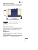
Step 1—Mount the Transceiver Use the supplied 6-32 x 1/4 inch (6 mm) screws to attach the mounting brackets to the bottom of the radio. Figure 1 shows the mounting dimensions of the unit. Mount the radio to a stable surface. (Fasteners not normally supplied.) Invisible place holder 2.75˝ (7 cm) 8 5/8˝ (21.8 cm) Figure 1. Transceiver Mounting Dimensions (Dimensions for AP and Remotes identical) CAUTION POSSIBLE EQUIPMENT DAMAGE Use only the supplied mounting bracket screws.
Step 3—Measure & Connect Primary Power The DC input power to the transceiver must be within 10–30 Vdc and capable of continuously providing at least 2.5 Amperes. A power connector with screw-terminals is provided with each unit. Strip the wire leads to 6 mm (1/4 inch). Be sure to observe proper polarity as shown in Figure 2 with the positive lead (+) on the left side; negative on the right side. Invisibleplaceholder Figure 2.
Other parameters commonly needing review or adjustment are: • RF Output Power Level (AP Only)—Check and adjust as necessary for compliance with regulatory limits. (Default power is +30 dBm for 900 model, +20 dBm for 3650 model.) Note that Remotes “auto-adjust” power output based on target receive signal set at the Access Point. • Password—Used for remote access and Menu System features. • Frequency Mode (900 model only)—This is found under Radio Configuration Menu>Frequency Control.
Log-in and Configuration Procedure The following is an overview of the local log-in and configuration procedure using the COM1 serial port. For detailed instructions on this, and other methods of control, refer to the Mercury Reference Manual. a. Connect a computer’s serial port to the COM1 Port of the radio. b. Launch a terminal communication program, such as HyperTerminal, on the computer. (Configure terminal to: 115,200 bps/8N1/no handshaking/VT100.) c. Press the ENTER key.
NOTE: Using Configuration Scripts under the Maintenance/Tools menu will aid in uniformly configuring multiple units. See the Mercury Reference Manual for details. Step 5—Connect the Data Equipment Connect Ethernet-compatible data equipment to the unit’s LAN port (10/100 BaseT), or one of the serial ports, depending on the capability of your transceiver.
Scanning—The unit is looking for an Access Point beacon signal. Ranging—Unit is adjusting power, timing, and frequency with an AP. Connecting—Unit has an RF connection with the AP. Authenticating—(When Device Authentication is in use) The Remote is authenticating itself to the network to obtain security clearance. Associated —The unit has successfully synchronized and associated with an Access Point. This is the normal status.
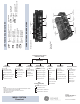
TX/RX1 ANTENNA PORT DC POWER INPUT (10—30 VDC, 2.5A) COM1 SERIAL PORT DC POWER INPUT (10—30 VDC, 2.5A) LED INDICATOR PANEL GPS ANTENNA CONNECTION WiFi ANTENNA PORT RX2 ANTENNA PORT LAN PORTS USB PORTS (Mini-A, Type-A) TX/RX1 ANTENNA PORT RX2 ANTENNA PORT GPS ANTENNA CONNECTION LED INDICATOR PANEL COM1 SERIAL PORT LAN PORT Option Set 1 Remote Standard Unit CONNECTORS AND INDICATORS ...ON ............Has satellite fix Flashing ....Synchronizing OFF ..........No satellite fix GPS COM1 ...
INSTALLATION REFERENCE CHART Detailed instructions are contained in the Reference Manual, P/N 05-4446A01 INSTALLATION SUMMARY Step 1 – Mount the Transceiver Step 2 – Install the Antennas ANTENNA SYSTEM Step 3 – Measure & Connect Primary Power (10–30 Vdc) Step 4 – Review the Transceiver’s Configuration RTU/PLC Network Name—Unique name for each radio network. Required for (Crossover Cable to Radio) Remotes to associate with the Access Point. (Default name is MDS-Mercury.
In general, signal levels stronger than –80 dBm will provide reliable communication in the network. RSSI measurements and Wireless Packet Statistics are based on multiple samples over a period of several seconds. The average of these measurements is displayed by the RSSI screen. In the steps below, the path to the Menu System item is shown in bold text. Procedure 1. Verify the Remote is associated with an Access Point unit by observing the LINK LED. It should be on or blinking. 2.
TRANSMITTER POWER & ANTENNA TEST The following procedure may be used to measure the transmitter’s RF power output and SWR “match” of the antenna system. A directional wattmeter is required for the test, such as a Bird Model 43, with an appropriate element installed. Before you start, keep in mind that using the Test Mode will disrupt network operation. Procedure 1. Connect a directional wattmeter between the ANTENNA port and the antenna system. 2. Place the transceiver into the Radio Test Mode.
TROUBLESHOOTING It is best to begin troubleshooting at the Access Point, as the rest of the system depends on it for network synchronization and configuration. If the Access Point has problems, the operation of the entire network will be affected.
Table 1. Troubleshooting Using LEDs (Continued) Symptom Problem/Recommended Checks LINK LED not lit. a. Network Names of APs and Remotes do not match. They must be identical for association to occur—Also, verify that the system has a unique Network Name. b. Remote not yet associated with an Access Point with the same Network Name. Check the “Status” of the unit’s process of associating with the Access Point. Use the Menu System. c. Poor Antenna System—Check the antenna, feedline and connectors.
Table 2. Troubleshooting with the Menu System Symptom Problem/Recommended System Checks Cannot Access the Remote or AP through COM1 Only occurs in three possible scenarios: —COM1 is damaged or the Unit is faulty. —COM1 is being used for Streaming GPS information to Console terminal. —COM1 is being used for serial data. a. Connect to unit via Telnet or Web browser b.
SPECIFICATIONS GENERAL Temperature Range: –40° C to +70° C (–40° F to 158° F) Humidity: 95% at +40° C (104° F); non-condensing Primary Power: 10–30 Vdc External Power Supply Options: 48 Vdc; 110–120/210–220 Vac Typical Current Consumption (assumes 1 Watt RF Output): Mode DC Power 13.8 Vdc 24 Vdc AP Transmit 25 W 1.8 A 1.0 A AP Receive 8W 579 mA 333 mA RM Transmit 25W 1.8 A 1.0 A RM Receive 6.5W 471 mA 270 mA Size (without mtg. hardware): Mounting Options: Weight: Case: 5.
PHYSICAL INTERFACE: Ethernet: 10/100BaseT, RJ-45 Serial: (COM1) RS-232, DB-9F APPROVALS: FCC Part 15.247 (DTS) CSA/US Class 1, Div. 2 Industry Canada RS-210 PROTOCOLS: Ethernet: IEEE 802.3, Spanning Tree (Bridging), VLAN, IGMP TCP/IP: DHCP, ICMP, UDP, TCP. ARP, Multicast, SNTP, TFTP MANAGEMENT: Serial: Encapsulation over IP (tunneling) for serial async multidrop protocols including Modbus, DNP.
TECHNICAL ASSISTANCE Technical assistance is available from our Technical Support Department during business hours (8:30 A.M.–7:00 P.M. Eastern Time). When calling, please give the complete model number of the radio, along with a description of the trouble symptom(s) that you are experiencing. In many cases, problems can be resolved over the telephone, without the need for returning the unit to the factory. Phone: 585 241-5510 E-Mail: TechSupport@GEmds.com FAX: 585 242-8369 Web: www.GEmds.
GE MDS, LLC 175 Science Parkway Rochester, NY 14620 General Business: +1 585 242-9600 FAX: +1 585 242-9620 Web: www.GEmds.