
Installation guide


Before you begin - Readthese instructions completely and carefully.
IMPORTANT:Savethese instructions for local inspector's use.
IMPORTANT:OBSERVEALLGOVERNINGCODESAND ORDINANCES,
NOTETOINSTALLER:Be sure to leave these instructions with the consumer
NOTETOCONSUMER:Keepthese instructions with your Use and Care Book for future reference.
If you have questions concerning the installa-
tion of this product, call the GE Answer
Center@ Consumer lnfi_rmation Service at
800.626.2000, 24 hours ada> 7 clays a week.
If vou received a damaged oven, you should
contact your dealer.
Proper installation is the responsibility of the
installer. Product failure due to improper
installation is not covered under the GE
Appliance _:alTantv. See the Use & Care
Guide tor warranty information.
hnportant
S(qety
h brmation
Safety Instructions
This product requires a three prong
grotmded receptacle. The installer must
perform a ground continuity check on the
power outlet box befiwe begim_ing the
installation to insure that the outlet box is
properly grounded. If not properly grounded,
oi" if the outlet box does not meet the
electrical requirements noted, (under
ELECTRICAI_ REQUIREMENTS), a qualified
electrician should be employed to correct anv
deficiencies.
CAUTION: Forpersonal safety, removehousefuse or ovencircuit
breaker before begieeieg iesta%tion to avoid severe orfatal
shock injury.
CAUTION: Forpersonal safety, the mounting surface must be
capable of supporting the cabinet load, in addition to the added
weight of this 70 poued product,plus additional oveeloads of up
to 50 pouedsor a total weight of 120 pounds.
CAUTION: Forpersonal safety this product cannot be installed in
cabinet arrangements suchas ae island, apeninsula or below
acountertop.
Electrical Requirements
Product rating is 120 w_lts AC, 60 Hertz, 13
amps. mad 1.45 kilowatts. This product must
be com_ected to a supply circuit of the proper
voltage and fl'equency, Wire size must con-
fiwm to the requirements of the National
Electric Code or the prevailing local code tor
this kilowatt rating. The power supply cord
and plug should be brought to a separate l 5
or 90 ampere branch circuit single grotmded
receptacle, The outlet box should be located
near the cord entry point, The outlet box and
supply circuit should be installed by a quali-
fied electrician and conliwm in the National
Electric Code or the prevailing local code.
Usage: Can be installed over any GE single
electric built-in oven.
Con_n_
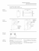
DesignInformation
Product Dimensions.........................................................................................................................................................................3
Cutout Dimensions ...........................................................................................................................................................................3
Electrical Locations .........................................................................................................................................................................3
Advance Planning ............................................................................................................................................................................3
Installation
Installation Option ............................................................................................................................................................................4
Tools and Materials Required ........................................................................................................................................................4
Parts Supplied ...................................................................................................................................................................................4
Step 1,Slide Microwave into the Cutout ......................................................................................................................................4
Step 2, Remove Grille Retainer Screws ........................................................................................................................................5
Step 3, Install Side Trim for 30"Appearance ...............................................................................................................................5
Step 4, Drive Installation Screws ..................................................................................................................................................5
Step 5, Reinstall Grille......................................................................................................................................................................6