
Installation Guide

GEH-3792D
INSTRUCTIONS
FILTR•GARD
®
LUMINAIRE
READ THOROUGHLY BEFORE INSTALLING
THE OPERATING TEMPERATURE “T-CODE” LISTED FOR THIS
LUMINAIRE IS BASED ON THE FOLLOWING BULB SIZES.
USE OF OTHER THAN THESE MAY RESULT IN A HIGHER
OPERATING TEMPERATURE AND COULD RESULT IN A
HAZARDOUS CONDITION.
LAMP TYPE WATTAGE BULB SIZE
HIGH PRESSURE SODIUM 70,100,150 ED 23 1/2
HIGH PRESSURE SODIUM 250, 400 ED 18
METAL HALIDE/MERCURY 175, 250 ED 28
METAL HALIDE/MERCURY 400 ED 37
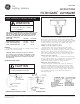
GENERAL
A complete luminaire consists of a ballast housing, optical
assembly, and a cover/mounting.
CAUTION: When installing luminaire in hazard-
ous locations check operating temperature limits
prior to installation to insure it conforms to the
environmental temperature restrictions and NEC
classifications
MOUNTING INSTALLATION
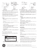
Pendant and Low Profile Cover (See Figure 1)
Remove wiring box door, and thread cover onto conduit.
Orient cover, seal around the conduit using approved NEC
procedures. Tighten set screw at mounting hub. Wiring should
be accomplished in accordance with accepted NEC practices.
A factory attached ground lead is provided. After wiring
replace the wiring compartment door.
Flexible Cover (See Figures 2 and 3)
Remove wiring box door. Loosen four(4) bolts holding
mounting hub to cover. Position adapter plate correctly to
balance luminaire. Use widest bolt spacing possible to secure
plate to cover. Wiring should be accomplished in accor-
dance with accepted NEC practice. Factory attached ground
lead is provided. After wiring, replace the wiring box door.
Ceiling Cover (See Figure 4)
Using the tabs, mount cover to ceiling and remove wiring
box door. Wiring should be accomplished in accordance with
accepted NEC practices. Factory attached ground lead is
provided. After wiring, replace the wiring box door.
Wallmount Cover (See Figure 5)
Mount wiring box and pull leads. Tether is supplied to
hold arm assembly while wiring. Wiring should be accom-
plished in accordance with accepted NEC practices. Factory
attached ground lead is provided. After wiring, attach arm
assembly to wiring box. Do not damage gasket attached to
arm assembly. Mounting screws should be tightened in
alternate sequence.
CAUTION
Unit will fall if not installed properly
• Follow installation instructions
WARNING
Risk of electric shock
• Turn power off before servicing
– see instructions
PENDANT AND LOW PROFILE COVER
Figure 1
FLEXIBLE COVER
Figure 2
Figure 3
These instructions do not purport to cover all details or variations in equipment nor to provide for every possible contingency to be met in connection with installation, operation or
maintenance. Should further information be desired or should particular problems arise which are not covered sufficiently for the purchaser’s purposes, the matter should be referred
to GE Lighting Solutions.
g
GE
Lighting Solutions