
Technical Specifications


Masoneilan 21000 Series Top Guided Globe Valve | 5
© 2014 General Electric Company. All rights reserved.
B. Screwing Stem to Plug
•
Hold the plug (with vise jaw assembly) in a vise.
•
Lock two nuts against each other on the end of the new
plug stem, and screw the stem solidly into the plug using a
wrench on the upper nut.
When properly assembled, the reference mark (see Section A
above) should be flush with the end of the plug guide.
C. Drilling the New Parts
• If the plug is already fully drilled (typical for 440 C hardened
stainless steel material or solid Stellite or Equivalent), then
drill the stem to the same diameter (Diameter C in Figure 9)
as the plug shank hole.
• Iftheplugguideareahasacentermark,
PIace the plug guide on a V-block and use a suitable drill
size to either:
— Match the hole size in the plug, or
— Match Diameter C (see Figure 9)
Drill through the plug-stem assembly.
• If the plug guide area does not have any hole or any
center mark,
— Measure Dimension D based on the plug guide diameter
and stem diameter (see Figure 9).
— PIace the plug guide on a V-block, and make a center
mark on the plug guide area using a center punch.
— Drill through the plug-stem assembly using a suitable size
drill bit.
In all cases after drilling: Remove any burrs from the plug
guide hole by making a slight chamfer.
D. Pinning the Plug-Stem Assembly
1.
Select the correct size pin based on the plug guide diameter
and stem diameter (see Figure 9). Apply a small amount of
grease on the pin and hand assemble it into the hole in the
plug.
2. Press fit the pin into the hole using a hammer. Complete
the pinning operation by taking care to ensure that the pin
is recessed by the same amount at both sides (see Figure
9).
3. After the plug has been pinned, it should be placed in a
lathe to ensure it is concentric with the stem.
If the assembly is not running true, then the stem should
be placed in a collet with the plug guide against it and the
plug should be adjusted. Alignment of plug stem can be
performed by means of a soft faced mallet.
Replacing Existing Stem Only
A. Removing Existing Pin and Stem
1.
Place the plug guide on a V-block and use a drift punch to
drive out the old pin.
Note: If it is necessary to drill out the pin, use a drill bit
slightly smaller than the pin diameter.
2. Hold the plug guide in a vise (see note on opposite side of
page).
3. Lock one nut against another at the end of the plug stem.
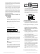
7. Fasten the bonnet to the body using four body stud
nuts (10) spaced equally apart. Apply slight pressure
and tighten evenly.
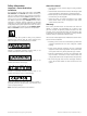
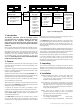
CAUTION
CAUTION
WARNING
DANGER
Do not tighten nuts to final torque specifications at
this time. The bonnet is used temporarily for guiding
purposes only.
8. Insert two or three pieces of packing into the packing box
to assist in guiding the stem and plug during lapping.
9. Screw a drilled and tapped rod with a T-handle onto the
plug stem and secure with a locknut (see Figure 4).
Note: As an alternative, drill a hole through a flat steel
plate and fasten to the plug stem using two locknuts.
10. Apply slight pressure on the stem, and rotate the stem
in short oscillating strokes (around 8 to 10 times).
Repeat this step as necessary.
Note: The plug should be lifted and turned 90° each
time before repeating Step (10). This intermittent lifting
is required to keep the plug and seat ring concentric
during lapping.
11. After completion of the lapping operation, remove
bonnet and internal parts. The seating area of the
seat ring and the plug must be cleaned of all lapping
compound in preparation for reassembly.
7.4 Lo-dB PIug (Figure 8, 14 or 15)
The procedures used for performing maintenance on a valve
equipped with Lo-dB plugs (21700/21800/21900 Series) are the
same as those used for Threaded or Quick Change Trim.
CAUTION
CAUTION
WARNING
DANGER
Maintenance of the plug should be limited to cleaning of the
ports and the procedures defined under Sections 7.3 (Lapping)
and 7.5 (Pinning) as required.
7.5 PIug Stem Pinning
Plug stem pinning in the field may be required for the following:
— Replacing existing plug and stem, or
— Replacing existing stem only
Replacing Plug and Stem
If it is necessary to replace the plug, then the plug stem
must be replaced at the same time. The original pin hole in
an existing stem will not provide the necessary fit, and might
seriously impair the strength of the assembly.
A. Reference Marking on the Plug Stem
Measure the depth of the pilot recess in the plug (Dimension X
in Figure 9), and make a reference mark on the plug stem at the
same distance from the thread.
Note: While pinning is being performed, care must be taken not
to damage the seating surface or plug guide. Always use a soft
metal or plastic vice jaws with cylindrical features to hold the
plug guide area (see Figure 9).