
Technical Specifications


2 | GE Oil & Gas © 2014 General Electric Company. All rights reserved.
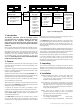
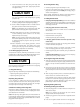
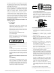
Figure 1 - Numbering System
cage with an anti-cavitation cage permits the pressure drop to
be split between the two stages efficiently.
The 21900 Series double stage Lo-dB valve is also derived from
the 21700 single stage Lo-dB valve through a modification to the
cage and plug. Substitution of the standard cage, with a Lo-
dB cage permits the pressure drop to be split between the two
stages efficiently.
In the 21800/21900 Series designs, enlargement of the plug head up
to the cage diameter permits simultaneous throttling of the plug C
v
and the cage C
v
. It also provides optimum allocation of the pressure
drop between the two stages along the entire plug travel.
Recommended spare parts required for maintenance are listed
in the Parts Reference table on page 17. The model number,
size, rating and serial number of the valve are shown on the
identification tag located on the actuator. Refer to Figure 1 for the
21000 series numbering system.
3. Unpacking
Care must be exercised when unpacking the valve to prevent
damage to the accessories and component parts. Should any
problems arise, contact your local GE's Masoneilan representative
or sales department.
4. lnstallation
4.1 Before installing the valve in the line, clean piping and
valve of all foreign material such as welding chips, scale,
oil, grease or dirt. Gasket surfaces should be thoroughly
cleaned to ensure leak-proof joints.
4.2 To allow for in-line inspection, maintenance or removal of
the valve without service interruption, provide a manually
operated stop valve on each side of the 21000 Series
valve with a manually operated throttling valve mounted in
the by-pass line (See Figure 2).
4.3 The valve must be installed so that the controlled
substance will flow through the valve in the direction
indicated by the flow arrow located on the body.
• Withcontouredplug(21100/21600)
or Lo-dB plug (21700/21900) :flow-to-open
• Onanti-cavitationdesign(21700/21800) :ow-to-close
1. lntroduction
The following instructions should be thoroughly reviewed
and understood prior to installing, operating or performing
maintenance on this equipment. Throughout the text,
safety and/or caution notes will appear and must be strictly
adhered to, otherwise, serious injury or equipment malfunction
could result.
GE has a highly skilled After Sales Department available for start-
up, maintenance and repair of our valves and component parts.
Arrangements for this service can be made through your local GE's
Masoneilan representative or sales department. When performing
maintenance use only Masoneilan replacement parts. Parts
are obtainable through your local representative or spare parts
department. When ordering parts, always include Model and Serial
Number of the unit being repaired.
2. General
These installation and maintenance instructions apply to all sizes
and ratings of the 21000 Series control valves regardless of the
type of trim used.
21000 Series single ported top guided control valves are designed
with built in versatility making them well-suited to handle a wide
variety of process applications.
Standard construction offers a contoured plug (21100 Series) with a
threaded seat ring or a quick change seat ring. The heavy top plug
guiding provides maximum support to ensure plug stability.
A series of reduced area trim is available to provide wide flow
range capabilities in all valve sizes.
Tight Shutoff Class IV leakage is standard. Optional constructions
(one of which is the 21600 Series soft seat plug) meet IEC 534-4 and
ANSI/FCI 70.2 Class V and Vl requirements.
An optional Low Emission LE
®
Packing is available to assure
compliance with the fugitive emission containment requirements.
Replacing the conventional plug with the single stage Lo-dB
design (21700 Series) provides excellent noise attenuation or
anti-cavitation performance.
The 21800 Series double stage anti-cavitation valve is derived
from the 21700 single stage anti-cavitation valve through a
modification to the cage and plug. Substitution of the standard
2nd
Flow
Characteristics
0. Undefined
1. Linear
2. Equal
Percentage
3. Modified
Percent
2nd
5th
4th
3rd
87 Spring Diaphragm
Air to Close
88 Spring Diaphragm
Air to Open
1st
1st
Plug Type
0. Undefined
1. Contoured
6. Soft Seat
7. Single Stage
Lo-dB/
Cavitation
Containment
8. Double Stage
Cavitation
Containment
9. Double Stage
Lo-dB
Actuator Type
Seat Type
0. Undefined
4. Quick Change
5. Threaded
6th
Optional
Configuration
A Angle Body
BS Bellows
Seal
EB Extension
Bonnet
C Cryogenic
Extension
Bonnet
Body
Series
21