
Technical Specifications

16 | GE Oil & Gas © 2014 General Electric Company. All rights reserved.
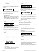
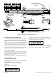
10.3 Plug and Seat Ring Seating Surfaces
It is not possible to lap the plug and seat ring seating
surfaces after the bellows has been assembled to the
stem.
If the seat ring shows signs of minor wear, it should be turned
on a lathe to clean up the worn area. The seating surface of
the seat ring is 30 degrees from centerline axis. However, no
more than 0.010 in. (0.25 mm) of material should be removed.
In cases where the seat ring cannot be repaired, or if the plug is
also damaged the only alternative is to replace both parts.
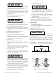
10.4 Bonnet Reassembly
Place new gasket (28) into the groove of the bonnet spacer.
Install the bonnet (25) and assemble nuts (27) and studs (26).
Bonnet must be positioned so the packing flange studs are at a
90° angle to the flow centerline.
Refer to table in Figure 11 for proper bolt torque and
tightening sequence.
10.5 Valve Body Reassembly
Refer to instructions stated in Section 8 for the specific trim
type involved.
10.6 Actuator to Body S/A and Plug Stem
Adjustment
Refer to instruction Ref. GEA19530.
Assembly of the No. 6 actuator on a bellows seal valve requires
a three-sectioned coupling. Follow coupling instructions as
described for the No. 10, 16 and 23 actuators.
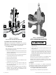
CAUTION
CAUTION
WARNING
DANGER
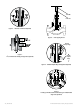
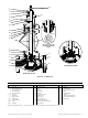
The bellows assembly causes a “spring back” effect. Measure this
plug spring back before referring to Instruction Ref. GEA19530. Be
sure to add this spring back length to the over seat adjustment.
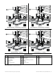
Pull plug out of the Bonnet
Extension (29) for access to
the plug pin
Lower Mechanical Stop
to Protect the Bellows
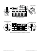
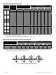
Plug and Plug Stem-Bellows S/A Stem
29
Plug Stem
Dia. “F”
Pin Hole
Dia. “C”
“D” “L”
Plug Guide
Dia. “E”
mmin.
22.227/8
38.101 1/2
60.322 3/8
69.852 3/4
=
=
Soft metal
or plastic
vise jaws
Cylindrical machining
diameter of the jaws
=
plug guide diameter “E”
C Dia.
D
F Dia.
L
E Dia.
30
28
17
16
mm
12.70
12.70
19.05
19.05
in.
1/2
1/2
3/4
3/4
mm
3.50
3.50
5.00
5.00
in.
.138
.138
.197
.197
mm
42
55
70
70
in.
1.65
2.17
2.75
2.75
mm
18
32
50
50
in.
.70
1.25
2.00
2.00
Figure 18 - Unpinning and Pinning of the Plug to Stem