
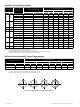
Technical Specifications

14 | GE Oil & Gas © 2014 General Electric Company. All rights reserved.
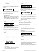
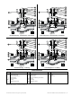
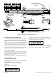
Figure 16 - 21000 Series
3/4" to 2" Valve Sizes ANSI Class 900 to 2500
Figure 17 - Angle Body Design
3/4" to 6" Valve Sizes ANSI Class 150 to 600
3/4" to 2" Valve Sizes ANSI Class 900 to 2500
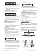
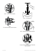
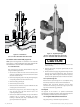
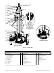
10.1 Bellows Valve Disassembly (Figure 19)
Note: Spiral wound gaskets are standard in the 21000 BS
Series design. IT IS RECOMMENDED THAT NEW GASKETS ARE
INSTALLED EACH TIME THE VALVE IS DISASSEMBLED.
10.1.1 Threaded Trim
After removing the actuator, disassemble the body S/A
using the following procedure:
• Disconnect the leak-off circuit from the bonnet (if this
option is included). Remove nuts (27) and bonnet studs
(26) from the bonnet (25).
• Remove packing flange stud nuts (3), packing flange (4)
and packing follower (5). Remove bonnet (25).
• Remove existing packing (6).
• Remove body stud nuts (10).
• Remove bonnet extension (29), stem bellows S/A (30)
and plug (16) at the same time.
• Remove the plug pin (17), then remove the plug (16)
from the plug stem (30). (See section 10.2.1.1 for
unpinning the plug stem).
• Remove stem bellows S/A (30) by the top of the bonnet
extension (29). If necessary, disengage the upper
bushing of assembly (30) using a screwdriver in the
groove provided for this purpose.
CAUTION
CAUTION
WARNING
DANGER
Be careful not to damage the seating surfaces of the
bellows bushing.
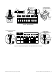
• Remove the bonnet and spacer gaskets (28) and the
body gasket (11).
• Bonnet extension (29), plug (16), guide bushings and seat
ring (14) may now be inspected for wear and service
damage. After determining the maintenance required,
proceed to the appropriate section of these instructions.
10.1.2 Quick-Change Trim
Removal of the quick-change trim is accomplished using
the same procedures as removal of the threaded trim.
However, after the bonnet extension (29) has been
removed from the body, remove the cage (13), the seat
ring (14) and the seat ring gasket (15).
10.2 Repair
The purpose of this section is to provide recommended
maintenance and repair procedures. These procedures assume
the availability of standard shop tools and equipment.
10.2.1 Plug/Stem Bellows/Bonnet Extension S/A
Plug stem pinning in the field may be required for: