
Technical Specifications
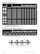

Masoneilan 21000 Series Top Guided Globe Valve | 9
© 2014 General Electric Company. All rights reserved.
I. Install packing flange stud nuts (3).
CAUTION
CAUTION
WARNING
DANGER
Do not overtighten (See Section “7.6. Packing Box”).
J. If a leak detection connection was installed, connect it on
the lateral NPT port in the bonnet. If not, ensure that the
1/4" NPT plug remained in place (Figure 5).
K. For actuator assembly and plug stem adjustment, proceed
to the actuator instruction Ref. GEA19530 for a type 87/88
multispring actuator.
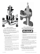
8.3 High Pressure & Angle Design (Figures 16 & 17)
Standard trim is used within these optional body configurations.
Refer to the applicable sections within this instructions manual.
9. Actuators
9.1 Types 87/88 Actuators
Refer to Instruction Ref. GEA19530 for removal, maintenance,
assembly and adjustment.
10.Bellows Seal Assembly
CAUTION
CAUTION
WARNING
DANGER
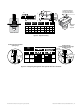
SINCE THIS IS A SEALING
BELLOWS, THE PLUG STEM SHOULD NEVER BE TURNED UNDER
ANY CIRCUMSTANCES.
There is a built-in anti-rotation feature, consisting of a double flat
surface machined on the plug stem that slides into a rectangular
slot machined in the upper bushing (30) of the bellows (see Figure
19 - Section a).
IT IS IMPORTANT TO DISCONNECT THE ACTUATOR FROM THE
VALVE BEFORE CHANGING THE ACTUATOR ROTATIONAL POSITION.
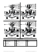
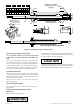
Figure 2 - Typical Installation
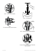
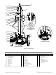
Insert
3
/4" - 2" Valve Sizes 3" - 8" Valve Sizes
Insert
Retainer
Plug
Tip
Plug Tip
O-ring
Shank
Skirt &
Insert
Retainer
Set
Screw
Set
Screw
Flats
Flats
Figure 3 - Soft Seat Plugs (Optional)
CAUTION
CAUTION
WARNING
DANGER
Tighten nuts (10) until metal to metal contact is obtained
with proper bolt torque. Refer to Figure 11 for proper bolt
torque and tightening sequence specifications.
G. lnsert packing (6) [and lantern ring (7) on valve equipped
with an optional lubricator connection]. Refer to Section
7.6 for proper packing assembly procedure for standard
or optional designs.
H. Install packing follower (5) and packing flange (4).
I. lnstall packing flange stud nuts (3).
CAUTION
CAUTION
WARNING
DANGER
Do not overtighten (See Section “7.6. Packing Box”).
J. If a leak detection connection was installed, connect it on
the lateral NPT port in the bonnet. If not, ensure that the
1/4" NPT plug remained in place (Figure 5).
K. For actuator assembly and plug stem adjustment, proceed
to the actuator instruction Ref. GEA19530 for a type 87/88
actuator.
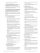
8.2 Quick-Change Trim (Figure 13 or 15)
A. CIean all gasket mating surfaces.
B. Install seat ring gasket (15) and seat ring (14).
Note: Spiral wound gaskets (11 & 15) are standard in the
21000 Series design. It is imperative that a new gasket be
installed each time the valve is disassembled.
C. Install cage (13).
D. Carefully install plug and stem assembly.
Note: Valve should be lapped before final assembly. See
Section 7.3.
Note: For 2" valves with C
v
30 Lo‑dB / Anti‑Cavitation trim
only, steps C and D must be reversed such that the plug
and stem assembly is installed prior to the cage.
E. Install body gasket (11).
F. Assemble bonnet (8) and body stud nuts (10) and tighten.
Bonnet must be positioned so the packing flange studs
are at 90° to the flow center line.
CAUTION
CAUTION
WARNING
DANGER
Care must be taken to ensure that the cage, seat, and
bonnet are properly aligned in the body. Cage should be
installed with parts at lower end, near seat ring. Tighten
nuts (10) until metal to metal contact is obtained with
proper bolt torque. Refer to Figure 11 for proper bolt
torque and tightening sequence specifications.
G. lnsert packing (6) [and lantern ring (7) on valve equipped
with an optional lubricator or leak detection connection].
Refer to Section 7.6 for proper packing assembly
procedure for standard or optional designs.
H. Install packing follower (5) and packing flange (4).