GE Oil & Gas Technical Specifications 10/2012 Masoneilan* Valves 21000 Series Control Valves Complete Line of Rugged, Top Guided, Globe Valves with Lo-dB* & Anti-Cavitation Capabilities
Table of Contents Numbering System...........................................................................................................................................................................3 General Data.......................................................................................................................................................................................3 Ratings/Connections(1)......................................................................................
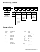
Numbering System 1st 2nd Actuator Type 1st Body Series 87 Spring Diaphragm Air to Close 21 88 Spring Diaphragm Air to Open 2nd Plug Type 3rd Flow Characteristics 4th 5th 6th Seat Type Optional Configuration 0. Undefined 0. Undefined 0. Undefined A Angle Body 1. Contoured 1. Linear 4. Quick Change 6. Soft Seat 2. Equal Percentage 5. Threaded BS Bellows Seal 7. Single Stage Lo-dB/ Anti-Cavitation 3. Modified Percent EB Extension Bonnet C Cryogenic 8.
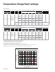
Temperature Range/Seat Leakage Contoured Trim Valve Size Inch 0.75 to 8 mm 20 to 200 Body (1) Rating ASME Class 150 to 2500 and equivalent PN Seat Type Metal Temperature Range (2) Packing Standard Bonnet Extension Bonnet min. max. min. max. PTFE, LE* or LE FireSafe Packing -20°F (-29°C) +450°F (+232°C) -100°F (-73°C) +800°F (+427°C) Graphite Packing -20°F (-29°C) +800°F (+427°C) -100°F (-73°C) +800°F (+427°C) Material min. -20°F (-29°C) Any +450°F (+232°C) -100°F (-73°C) max.
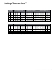
Ratings/Connections(1) Valve Size Inch mm ASME Class 150 (PN 20) RF SW THD RTJ ASME Class 300 (PN 50) BW RF SW THD ASME Class 600 (PN 100) BW RTJ RF SW THD RTJ BW 0.75 20 X X X X X X X X X X X 1 25 X X X X X X X X X X X 1.
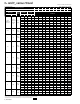
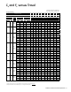
Cv and FL versus Travel Direction: FLOW-TO-OPEN (FTO) Flow Characteristic: LINEAR Contoured Trim Percent of Travel 10 20 30 40 50 60 70 80 90 100 FL 0.93 0.93 0.92 0.92 0.91 0.91 0.91 0.9 0.9 0.9 Valve Size Inch Close clearance 0.75 and 11 mm Close clearance 20 and 25 0.75 1 1.
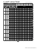
Cv and FL versus Travel Direction: FLOW-TO-OPEN (FTO) Flow Characteristic: EQUAL PERCENTAGE Contoured Trim Valve Size Inch 0.75 1 1.5 2 3 4 6 8 mm 20 25 40 50 80 100 150 200 Percent of Travel 10 20 30 40 50 60 70 80 90 100 FL 0.93 0.93 0.93 0.93 0.93 0.92 0.92 0.91 0.91 0.90 ASME Rating 150 1500 150 1500 150 1500 150 1500 150 1500 150 1500 150 -600 150 600 Orifice Diameter Travel Inch mm Inch mm RATED CV 0.25 6.4 0.8 20.3 0.05 0.08 0.11 0.
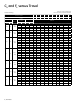
Cv and FL versus Travel Direction: FLOW-TO-OPEN (FTO) Flow Characteristic: MODIFIED PERCENT Contoured Plug Valve Size Inch 0.75 1 1.5 2 3 4 6 mm 20 25 40 50 80 100 150 8 | GE Oil & Gas Percent of Travel 10 20 30 40 50 60 70 80 90 100 FL 0.93 0.93 0.93 0.93 0.93 0.92 0.92 0.91 0.91 0.9 ASME Rating 150 1500 150 1500 150 1500 150 1500 150 1500 150 1500 150 600 Orifice Diameter Travel Inch mm Inch mm Rated Cv 0.25 6.4 0.8 20.3 0.04 0.07 0.14 0.
Cv and FL versus Travel Direction: FLOW-TO-CLOSE (FTC) Flow Characteristic: LINEAR TRIM Contoured Plug Valve Size Inch 0.75 1 1.5 2 3 4 6 8 mm 20 25 40 50 80 100 150 200 Percent of Travel 10 20 30 40 50 60 70 80 90 100 FL 0.53 0.56 0.60 0.68 0.75 0.78 0.81 0.84 0.85 0.86 ASME Rating 150 1500 150 1500 150 1500 150 1500 150 1500 150 1500 150 -600 150 600 Orifice Diameter Travel Inch mm Inch mm RATED CV 0.25 6.4 0.8 20.3 0.225 0.39 0.46 0.61 0.
Cv and FL versus Travel Direction: FLOW-TO-CLOSE (FTC) Flow Characteristic: EQUAL PERCENT Contoured Plug Valve Size Inch 0.75 1 1.5 2 3 4 6 8 mm 20 25 40 50 80 100 150 200 Percent of Travel 10 20 30 40 50 60 70 80 90 100 FL 0.53 0.53 0.55 0.63 0.72 0.80 0.80 0.80 0.80 0.80 ASME Rating 150 1500 150 1500 150 1500 150 1500 150 1500 150 1500 150 600 150 600 Orifice Diameter Travel Rated Cv Inch mm Inch mm 0.25 6.4 0.8 20.3 0.1 0.1 0.2 0.22 0.
Cv and FL versus Travel Contoured Plug Valve Size Inch 0.75 1 1.5 2 3 4 6 mm 20 25 40 50 80 100 150 Direction: FLOW-TO-CLOSE (FTC) Flow Characteristic: MODIFIED PERCENT Percent of Travel 10 20 30 40 50 60 70 80 90 100 FL 0.53 0.53 0.55 0.63 0.72 0.80 0.80 0.80 0.80 0.80 ASME Rating 150 1500 150 1500 150 1500 150 1500 150 1500 150 1500 150 600 Orifice Diameter Travel Inch mm Inch mm Rated Cv 0.25 6.4 0.8 20.3 0.06 0.09 0.19 0.3 0.5 0.73 0.99 1.
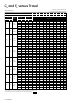
Cv and FL versus Travel Direction: FLOW-TO-OPEN (FTO) Flow Characteristic: LINEAR Rating: ASME 2500 (PN 420) Contoured Plug Valve Size Inch 0.75 1 1.5 2 mm 20 25 40 50 Percent of Travel 10 20 30 40 50 60 70 80 90 100 FL 0.93 0.93 0.92 0.92 0.91 0.91 0.91 0.9 0.9 0.90 ASME Rating 2500 2500 2500 2500 Orifice Diameter Travel Inch mm Inch mm Rated Cv 0.25 6.4 0.8 20.3 0.15 0.31 0.46 0.61 0.77 0.94 1.12 1.31 1.5 1.7 0.375 9.5 0.8 20.3 0.34 0.68 1.
Cv and FL versus Travel Direction: FLOW-TO-OPEN (FTO) Flow Characteristic: EQUAL PERCENT Rating: ASME 2500 (PN 420) Contoured Plug Valve Size Inch 0.75 1 1.5 2 mm 20 25 40 50 Percent of Travel 10 20 30 40 50 60 70 80 90 100 FL 0.93 0.93 0.93 0.93 0.93 0.92 0.92 0.91 0.91 0.90 ASME Rating 2500 2500 2500 2500 Orifice Diameter Inch mm Travel Inch Rated Cv mm 0.25 6.4 0.8 20.3 0.05 0.08 0.11 0.18 0.3 0.5 0.8 1.1 1.5 1.7 0.375 9.5 0.8 20.3 0.12 0.
Cv and FL versus Travel Direction: FLOW-TO-OPEN (FTO) Flow Characteristic: MODIFIED PERCENT Rating: ASME 2500 (PN 420) Contoured Trim Valve Size Inch 0.75 1 1.5 2 mm 20 25 40 50 Percent of Travel 10 20 30 40 50 60 70 80 90 100 FL 0.93 0.93 0.93 0.93 0.93 0.92 0.92 0.91 0.91 0.90 ASME Rating 2500 2500 2500 2500 Orifice Diameter Inch mm Travel Inch Rated Cv mm 0.25 6.4 0.8 20.3 0.04 0.07 0.14 0.28 0.5 0.73 0.99 1.28 1.52 1.7 0.375 9.5 0.8 20.3 0.
Cv and FL versus Travel Single Stage Lo-dB / Anti-Cavitation Trim Single Stage Cavitation Containment Valve Size Inch mm 0.75 20 1 1.5 2 3 4 6 8 Direction: FLOW-TO-OPEN (FTO) Lo-dB FLOW-TO-CLOSE (FTC) ANTI/CAV Flow Characteristic: LINEAR Percent of Travel 10 20 30 40 50 60 70 80 90 100 FL 0.93 0.93 0.93 0.93 0.93 0.93 0.93 0.93 0.93 0.93 ASME Rating Orifice Diameter Travel Inch mm Inch mm 150 2500 0.812 20.26 0.8 20.3 25 150 2500 0.812 20.26 0.8 20.
Cv and FL versus Travel Direction: FLOW-TO-CLOSE (FTC) Flow Characteristic: LINEAR Double Stage Anti-Cavitation Trim Valve Size inch mm Percent of Travel FL Orifice ASME Diameter Rating inch mm 10 20 30 40 50 60 70 80 90 100 0.975 0.975 0.975 0.975 0.975 0.975 0.975 0.975 0.975 0.975 Travel inch 0.75 20 1502500 0.812 20.6 0.8 20.3 1 40 1502500 0.812 20.6 0.8 20.3 20.6 0.8 20.3 40 1502500 0.812 1.5 2 50 3 4 80 100 1502500 1501500 1501500 1.25 31.8 0.8 20.3 1.
Materials of Construction 1 2 3 4 19 5 6 7 8 9 18 10 17 11 16 12 15 13 14 Standard Construction Spring Loaded Follower S/A Kalrez / Vespel Packing Set 5 pieces 21000 Close Clearance Low Flow Trim Soft Seated Plug S/A LE* Packing System (Optional) Low Emission Stem Packing 21000 Series Control Valves Technical Specifications | 17
Materials of Construction Standard Carbon Steel Version 650°F 800°F (343°C) (427°C) D D Description 450°F (232°C) D Ref. No.
Materials of Construction Standard Stainless Steel Version Standard Materials 650°F (343°C) D D Description 450°F (232°C) 800°F (427°C) D Ref. No.
Materials of Construction Standard Chrome Moly Version D D Description 450°F (232°C) 650°F 800°F (343°C) (427°C) D Ref. No.
Materials of Construction NACE Materials Construction Description 1 Plug Stem 2 Packing Flange Stud 3 Packing Flange Nut D Temperature Range -20°F (-29°C) NACE Materials(1) SOLUTION ANNEALED 316 STAINLESS STEEL ASTM B637 ALLOY (2) ASTM A193 GRADE B8 CLASS 1 (3) ASTM A193 GR B7M ZINC PLATING (4) ASTM A194 GRADE 8 (3) ASTM A194 GR 2HM ZINC PLATING (4) 4 Packing Flange ASTM A216 GRADE WCC ZINC PLATING 5 Packing Follower SOLUTION ANNEALED 304 STAINLESS STEEL Packing P
Materials of Construction Cryogenic Construction -320°F (-196°C) D D Description (3) (4) -50°F -20°F (-46°C) (-29°C) D Ref. No.
Bellows Seal Design Features 21000 BS Series Standard Construction Smart Solution Bellows seal configuration is fully compatible with the standard 21000 Series trim and actuator options providing equivalent capacity capabilities for each valve size. The standard packing box design and packing design options are used as a secondary stem seal. Bellows installed cycle life can be monitored in the field by utilizing Masoneilan’s SVI* Digital Positioner with actual process data.
Materials of Construction 31 25 26 28 27 30 29 Bellows Seal Construction 24 | GE Oil & Gas
Materials of Construction Bellows Seal - Carbon Steel Body Version (1) 25 26 27 28 29 D Temperature Range -20°F (-29°C) Description Materials Valve Bonnet Bonnet Stud Bonnet Stud Nut Bonnet Spacer Gasket Carbon Steel Upper Flange Bonnet Spacer Extension Lower Flange Assembly Stem Stainless Steel Bellows and Stem Assembly Hastelloy C(3) Bellows and Stem Assembly 30 Monel 400 (3) Bellows and Stem Assembly Inconel 625 (3) Bellows and Stem Assembly 31 Ref. No.
Materials of Construction Bellows Seal - Stainless Steel Body Version (1) -20°F (-29°C) 650°F (343°C) Temperature Range Description Materials D 25 26 27 28 29 Valve Stud Bonnet Stud Bonnet Stud Nut Bonnet Spacer Gasket Carbon Steel Upper Flange Bonnet Spacer Extension Lower Flange Assembly Stem Stainless Steel Bellows and Stem Assembly ASTM A351 GRADE CF8M or ASTM A182 GRADE F 316 ASTM A193 GR B7 – ZINC PLATING ASTM A193 GRADE B7 ASTM A194 GR 2H – ZINC PLATING ASTM A194 GRADE 2H 316L
Dimensions (inches) C C C B B D A A A D Flanged Butt, Socket Weld or Threaded Ends Extension or Bellows Bonnet Angle 21000 Series Dimensions (inches) A Valve Size (inches) 0.75 1 1.5 2 3 4 6 8 ASME Class ASME Class ASME Class 150-600 900-1500 2500 (PN 20-100) (PN 150-250) (PN 420) BW, SW, THD 8.24 8.24 9.88 11.24 13.24 15.5 20 24 BW, SW, THD 8.5 8.5 9.25 11.5 12.52 14.49 BW, SW, THD 12.5 12.5 13 14.
Dimensions (inches) C C C B B D A A A D Flanged Butt, Socket Weld or Threaded Ends Extension or Bellows Bonnet Angle 21000 Series Dimensions (inches) C Valve Size (inches) 0.75 1 1.5 2 3 4 6 8 Standard Bonnet ASME Class 150-600 (PN 20-100) 5.51 5.51 5.51 5.51 8 8.07 11.18 16.6 ASME Class ASME Class 900-1500 2500 (PN 150-250) (PN 420) 7.6 7.6 9 9 11.23 14.74 7.6 7.6 9 10.7 ASME Class 150-600 (PN 20-100) 9.92 9.92 9.92 9.92 13.9 15.87 16.69 22.
Dimensions (mm) C C C B B D A A A D Flanged Butt, Socket Weld or Threaded Ends Extension or Bellows Bonnet Angle 21000 Series Dimensions (mm) A Valve Size (mm) 20 25 40 50 80 100 150 200 ASME Class ASME Class 150-600 900-1500 (PN 20-100) (PN 150-250) BW, SW, THD 209 209 251 285 336 394 508 610 BW, SW, THD 216 216 235 292 318 368 ASME Class 2500 (PN 420) BW, SW, THD 318 318 330 375 ASME Class 150 (PN 20) RF RTJ 184 184 222 254 298 352 451 543 ASME Class 300 (PN 50) ASME Class 600 (PN 10
Dimensions (mm) C C C B B D D A A A Flanged Butt, Socket Weld or Threaded Ends Extension or Bellows Bonnet Angle 21000 Series Dimensions (mm) C Valve Size (mm) 20 25 40 50 80 100 150 200 Standard Bonnet Bellows Bonnet Cryogenic Extension Bonnet Extension Bonnet ASME Class 150-600 (PN 20-100) ASME Class 900-1500 (PN 150-250) ASME Class 2500 (PN 420) ASME Class 150-600 (PN 20-100) ASME Class 900-1500 (PN 150-250) ASME Class 2500 (PN 420) ASME Class 150-600 (PN 20-100) ASME Class 900-1
Weights Body S/A with Standard Bonnet (lbs) Valve Size (inches) ASME Class 150 – 300 (PN 20 – 50) FLG BW, SW & THD ASME Class 600 (PN 100) FLG BW, SW & THD ASME Class 900 – 1500 (PN 150 – 250) FLG BW, SW & THD ASME Class 2500 (PN 420) FLG BW, SW & THD 0.75 36 27 38 27 57 44 70 44 1 36 27 38 27 75 44 90 44 1.
Dimensions and Weights (in./lbs) XX D YY C Shown with optional Handwheel Dimensions and Weights Actuator Size Weights (lbs.) Actuator Dimensions (inches) A B (Model 88) C Standard D w/Handwheel 6 11.50 15.54 (17.52) 10.00 9.00 45 60 10 14.50 19.58 (21.54) 10.90 12.00 85 105 16 18.75 28.22 (30.79) 14.00 18.00 210 245 23 23.63 30.71 (33.27) 16.00 18.
Dimensions and Weights (mm/kg) XX D YY C Shown with optional Handwheel Dimensions and Weights Actuator Size Weights (kg) Actuator Dimensions (mm) A B (Model 88) C D Standard w/Handwheel 6 302 395 (445) 254 229 20 27 10 373 497 (547) 277 305 39 48 16 476 717 (782) 356 457 95 111 23 600 780 (845) 406 457 120 145 Actuator Removal Clearance = 152mm Limit Stops (mm) Up Stop Size Center of Gravity (mm) Without Handwheel Size X Y 6 5 248 10 0 3
* Masoneilan, LodB, LE, and SVI are trademarks of the General Electric Company. © 2012 General Electric Company. All rights reserved. Other company names and product names used in this document are the registered trademarks or trademarks of their respective owners.