GE Energy Management TM Maintenance Action Planner LTC-MAP 2130 Monitor Product Manual Part No. 70055MP Rev.
GE Energy Management LTC-MAP 2130 Monitor Maintenance Action Planner Monitoring System Product Manual 70055MP Revision D February 3, 2000
Copyright Information Copyright 2000 Reuter-Stokes, Inc. All rights reserved. This manual may not, in whole or part, be copied, photocopied, reproduced, translated or reduced to any electronic medium or machine readable form without prior consent, in writing, from Reuter-Stokes, Inc. The illustrations shown in this manual are intended solely to illustrate the text of this manual. Because of the many variables and requirements associated with any particular installation, Reuter-Stokes, Inc.
Table of Contents Section 1: Introduction Product Overview...................................................................................................................................................... 1-1 Specifications ........................................................................................................................................................... 1-3 Input.....................................................................................................................
Establishing Communications.............................................................................................................................. 3-20 Serial Port Communications ............................................................................................................................. 3-21 Modem Communications .................................................................................................................................. 3-22 Initial Start Up .....................
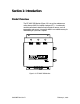
Section 1: Introduction Product Overview The LTC-MAP 2130 Monitor (Figure 1-1) is an on-line maintenance action planner (MAP) for load tap changers (LTC). It continuously monitors performance data from various types of sensors, such as temperature and current. It stores this data in non-volatile memory for downloading to a personal computer.
1-2 Section 1: Introduction LTC-MAP 2130 Monitor is a multi-input data storage and analysis system. Each system features: • • • • Seventeen (17) analog input channels. Sixteen (16) digital input channels (via optional Control Isolator). One (1) serial port/modem line. Two annunciator relay outputs (form C contacts). LTC-MAP 2130 uses state of the art technology to process, analyze, and store data into a configurable profile.
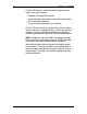
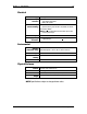
Section 1: Introduction 1-3 Specifications Input Analog Seventeen (17) channels. Channels 1 - 7 Input: 4 to 20 mA. Sample rate: 150 Hz. Channel 8 Input: ±10 VDC. Sample rate: 150 Hz. Channels 9-11 Configurable input: • 4 to 20 mA with a sample rate of 150 Hz, or • 5A AC (as monitored by a CT) with a sample rate of 1920 Hz. Channel 12 Configurable input: • 4 to 20 mA with a sample rate of 150 Hz, or • 50A AC (as monitored by a CT) with a sample rate of 1920 Hz.
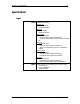
1-4 Section 1: Introduction General Relay Outputs Front Panel Indicators Display Two dry-contact relay outputs for alarm indication. Three LEDs: POWER: When lit, indicates that the monitor is receiving power. ALARM1: When lit, indicates that a software configurable alarm has been activated; contact relay driven. ALARM2: When lit, indicates that a software configurable alarm has been activated; contact relay driven. Front panel four line liquid crystal (LCD). Resolution: 1 V, 1 A, 1 °C.
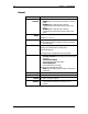
Section 1: Introduction 1-5 Electrical Sensor Power Supply Power Input Protection Power Input (Electrical Rating) 24 VDC @ 0.65A. Fused (F1) Type: AGC3 instant blow. Rating: 3A @ 250 V. AC: Standard: 120 VAC +10/-15%AC, 50 - 60 Hz. Optional (factory set): 240 VAC +10/-15%AC, 50 - 60 Hz. DC: 125 VDC +15%DC. NOTE: Monitors supplied with internal heater option must have AC power input. Power Consumption Supply Voltage Fluctuation Less than 16VA.
1-6 Section 1: Introduction Available Options Available options for the LTC-MAP 2130 are listed in Table 1-1. Refer to the applicable documentation for detailed information on the available options. Table 1-1: LTC-MAP 2130 Options Option Magnetic Mount RTD Temperature Sensor Part No.
Section 1: Introduction 1-7 Typical Application A transformer utilizing an LTC-MAP 2130 monitor is illustrated in Figure 1-2. The monitor is mounted on the transformer. Analog sensors mounted on the transformer are connected to the monitor. Refer to the example typical wiring diagram in Section 3 to determine specific sensor input connections.
1-8 Section 1: Introduction A typical system may include several monitors, one for each transformer at the site, multiplexed together. The multiplexer is typically located at the on-site substation. (See Figure 1-3). Data from all monitors on site may then be downloaded to a remote personal computer (PC). SAGE host software installed on the PC allows for data retrieval and analysis.
Section 1: Introduction 1-9 Manual Conventions This manual provides the information you will need to install, operate, and maintain the LTC-MAP 2130 Monitor. Throughout this manual CAUTIONS, WARNINGS, and NOTES are provided. CAUTION: Indicates a potentially hazardous situation which, if not avoided, may result in minor or moderate injury. WARNING: Indicates a potentially hazardous situation which, if not avoided, may result in death or serious injury. NOTE: Contains supplemental information.
Section 2: Getting Started Receiving Inspection On receipt of the LTC-MAP 2130 Monitor: 1. Carefully inspect the packing containers and contents for physical damage. 2. Carefully unpack the monitor, checking that all items listed on the packing slip are present and in good condition. NOTE: If damage is evident, or any items are missing, contact Support Services at (330-425-3755) for further instructions.
2-2 Section 2: Getting Started Front Cover Layout There are three indicator lights on the front cover of the LTC-MAP 2130 Monitor (see Figure 2-1): • The yellow POWER indicator illuminates whenever the monitor is receiving power. • The red ALARM1 indicator illuminates whenever a configured contact relay alarm is activated. • The red ALARM2 indicator illuminates whenever a configured contact relay alarm is activated.
Section 2: Getting Started 2-3 Face Panel Layout The face panel is accessed by releasing the fasteners on the right side of the front cover. The front panel features (see Figure 2-2): • A four-line LCD display. • Operating Conditions button. • Alarm Status & Settings button. • Acknowledge Alarm button. • A serial port. Present operating conditions, alarm settings, and alarm status may be viewed on the display by pressing the appropriate buttons.
2-4 Section 2: Getting Started Operating Conditions Button The Operating Conditions button is located directly below and left aligned with the display. Pressing the Operating Conditions button displays the sensor value readings. Four channels are displayed simultaneously. The display includes: • Channel number. • Channel name. • Present reading. • Units. After all sensor screens are displayed, pressing the Operating Conditions button again displays the tap change summary screen.
Section 2: Getting Started 2-5 LCD Display The LCD is a 20 character by 4 line display (Figure 2-3). It displays operating and status conditions. Screens are scrolled through using the Operating Conditions and Alarm Status & Settings buttons. L T C - MA P 2 1 3 0 r e v 2 1 3 0 . x x . y y c o p y r I g h t < Operating Conditions ( C ) 1 9 9 7 < Alarm Status & Settings Figure 2-3: Display with Control Buttons Serial Port CAUTION: The serial port and the modem cannot function simultaneously.
2-6 Section 2: Getting Started Circuit Board Location The CPU and I/O circuit boards are accessed by loosening the two thumb screws on the right side of the face panel (see Figure 2-4). The CPU circuit board is mounted to the back side of the face panel. The I/O Circuit board is mounted to the inside rear panel of the Monitor cabinet. The Power Supply board is mounted on the I/O Circuit board. A ribbon cable connects the CPU and I/O circuit boards.
Section 2: Getting Started 2-7 I/O Board The I/O Circuit board (Figure 2-5) contains sensor signal conditioning circuitry and hardware to interface to the sensors mounted on the transformer.
2-8 Section 2: Getting Started Power Supply Board The Power Supply circuit board (Figure 2-6) contains the low voltage supplies, incoming power terminals, and the power fuse (F1) for the monitor. F1 is a type AGC3 fuse, rated for 3 Amp at 250 V.
Section 2: Getting Started 2-9 CPU Board The CPU circuit board (Figure 2-7) contains the microprocessor (CPU), LCD Display, front panel buttons, and serial port.
2-10 Section 2: Getting Started Communications The SAGE host software installed on a personal computer allows for data retrieval and analysis. Communications with the LTC-MAP 2130 must be established in order to download data to the PC or upload configuration information to the terminal. Communication between the PC and the monitor can be established: • Directly via the front panel serial port and a null modem cable to a personal computer running the SAGE host software.
Section 3: Installation This Section includes procedures for installation, configuration, wiring, setting up communications, and initial start-up of the LTC-MAP 2130 Monitor. Selecting a Location The LTC-MAP 2130 is enclosed in a weatherproof stainless steel box that can be mounted indoors or outdoors. When selecting a mounting location for the monitor, verify that: • The mounting surface is able to support a minimum of 25 pounds (11.3 kg).
3-2 Section 3: Installation Mounting the Monitor Secure the monitor to the selected location using four ¼-20# stainless steels bolts through the mounting holes (see Figure 3-1). ½" (12.7 mm) 8" (203 mm) 1/4-20 UNF (4PL.) 12" (305 mm) 14" (356 mm) 1 ½" (38.1 mm) ½" (12.
Section 3: Installation 3-3 Cable Installation After securely mounting the LTC-MAP 2130 monitor, route the input and output cables back to the gland plate. CAUTION: Do not apply power to the LTC-MAP 2130 until all input and output cables are connected. The removable gland plate on the bottom of the LTC-MAP 2130 Monitor has pre-punched conduit holes (see Figure 3-2) and strain relief cable connectors. Weep holes are provided to allow drainage of excess moisture.
3-4 Section 3: Installation I/O Board Configuration Jumpers The I/O board configuration jumpers allow you to customize the LTC-MAP 2130 monitor to your application’s specific sensor (channel type input), alarm, and modem requirements. Channel Configuration Channels 9 through 12 are configurable for a 4-20 mA sensor input or a 5A/50A current input (as monitored through a CT). Channels 13 through 16 are configurable for a 4-20 mA sensor input or a voltage input.
Section 3: Installation 3-5 Table 3-1: Channel Configuration Jumpers and Positions Jumper JP1 JP2 JP3 JP4 JP5 JP6 JP7 JP8 JP9 Position A B A B A B A B A B A B A B A B A B Selected Input 5A (CT) Current Input A. 4-20 mA Sensor Input #9. 5A (CT) Current Input B. 4-20 mA Sensor Input #10. 5A (CT) Current Input C. 4-20 mA Sensor Input #11. 50 A (CT) Motor Current. 4-20 mA Sensor Input #12. Voltage Input 1. 4-20 mA Sensor Input #13. Voltage Input 2. 4-20 mA Sensor Input #14. Voltage Input 3.
3-6 Section 3: Installation Alarm Configuration Jumpers Jumpers JP18 and JP19 set the annunciator relay outputs to normal or inverted. Jumper JP13 configures the Acknowledge Alarm button. Refer to Table 3-3 for jumper positions. Refer to Figure 3-3 for jumper locations. NOTE: JP13 must always be installed. Table 3-3: Alarm Configuration Jumper JP18 JP19 JP13 Position INV NORM INV NORM Installed Removed Description Annunciator 1 Output Inverted. Annunciator 1 Output Normal. Annunciator 2 Output Inverted.
Section 3: Installation 3-7 Wiring Overview Prior to starting any wiring procedures: Pull the power fuse (F1) on the Power Supply board. • Securely ground the LTC-MAP 2130 at the ground lug. CAUTION: Pull the power board fuses or remove F1 on the I/O board before making connections. WARNING: The LTC-MAP 2130 Monitor must be properly grounded before placing the unit in service. An improper or missing ground can create a safety hazard. Refer to Figure 3-4 for fuse and ground lug locations.
3-8 Section 3: Installation C11 D10 R18 J1 RN6 TP1 J3 C4 J17 U5 TP3 C3 + C1 + R68 R67 U7 R70 CHANNEL 14 13 12 11 10 1 15 16 A B R69 JP9 JP7 C7 JP8 JP6 JP5 JP4 JP3 JP2 Power Fuse Type ADC2 Rated for 3A @ 250 V C2 + U1 17 J8 C16 U9 J6 C8 U6 TP2 RN1 J2 R15 C10 J7 JP13 U2 R17 Z1 C12 C4 9 A JP1 TP9 TP6 B J2 MOV1 J1 Power Input U2 C17 C9 U4 Sensor Ground 1/4-20 Stud LINE NEUT POWER J.W.HARLEY INC. 20065MPA 20065MPB ASSY NO.
Section 3: Installation 3-9 Figure 3-5: Example of a Typical Wiring Diagram for the LTC-MAP 2130 70055MP Revision D February 3, 2000
3-10 Section 3: Installation Wiring the Sensors Refer to Table 1-1 for a list of sensors available for use with the LTC-MAP 2130 Monitor. Detailed installation information for each sensor is provided in the referenced documentation. Some general notes to consider during sensor selection and installation: February 3, 2000 • Thermowell RTD sensors require a signal conditioning transmitter to provide a 4-20 mA output to the monitor.
Section 3: Installation 3-11 Wiring a Tap Position Indicator OEM Potentiometers The OEM potentiometer is a voltage divider containing a resistor string. Each position on the string represents a tap position. In the examples in this Section, the potentiometers have thirty three positions containing thirty two 40-ohm resistors. The actual number of positions and number and values of resistors may be different on your potentiometer. The power supplied to the OEM potentiometer depends on the utility.
3-12 Section 3: Installation 0 to +5 VDC or 0 to +10 VDC Power Connect the OEM potentiometer to the LTC-MAP Circuit Board, as follows (refer to Figure 3-6): 1. Connect the OEM Potentiometer Wiper to Sensor Input #8. 2. Connect the OEM Potentiometer 0 VDC Common Point to Sensor Common.
Section 3: Installation 3-13 -5 to +5 VDC or -10 to +10 VDC Power Connect the OEM potentiometer to the LTC-MAP Circuit Board, as follows (refer to Figure 3-7): 1. Connect the OEM Potentiometer Wiper to Sensor Input #8. 2. Connect the OEM Potentiometer Center Point to the Sensor Common.
3-14 Section 3: Installation LTC-MAP Power OEM potentiometers that are not powered require power from the LTCMAP’s 24 VDC Sensor Power Supply. To use the LTC-MAP supply, you must: • Select a Voltage Drop Resistor (Rd). • Connect the Power Supply wires to the OEM Potentiometer. • Connect the wires at the Monitor Circuit board. In order to use this power, you must first calculate the value of the required voltage drop resistor (Rd).
Section 3: Installation 3-15 3. Calculate the Voltage Drop Resistor value (Rd): Rd = Rs x 1.4. 4. Select a voltage drop resistor as follows: Resistance: first standard value greater than the Rd. Power rating: 2 watts. Tolerance: 5% or less As an example, consider a potentiometer with thirty-two 40 ohm resistors. The calculated string resistance would be: Rs = (40 ohms) x (32 Resistors) - 1280 ohms. And Rd = Rs x 1.4 = 1280 x 1.4 = 1792 ohms. The next standard resistor value greater than 1792 is 1800 ohms.
3-16 Section 3: Installation After-Market Use the following procedure to wire an After-Market Tap Position Indicator. 1. Verify that the signal output is one of the following: • - 5V to + +5 VDC • -10 to + 10 VDC, • 0 to +5 VDC, or • 0 to +10 VDC. 2. Connect the signal output to Sensor Input #8. 3. Connect the signal reference to a Sensor Common Terminal. NOTE: Tap Position must be calibrated to operate correctly (see Calibrate Tap Position).
Section 3: Installation 3-17 Wiring the AC Voltage Inputs Connect voltage signals to the designated terminals (Voltage Input #1, #2, #3, #4) on the wiring and installation diagrams. Refer to Figure 3-5 for terminal location. NOTE: The signal specification range for Voltage Inputs #1, #2, #3, and #4 are 0 to 300 Vrms. If your signal input is different, contact Support Services as noted on back cover. Wiring the AC Current Inputs There are two types of current inputs - powered CT and unpowered CT (e.g.
3-18 Section 3: Installation Wiring the Annunciator Outputs Wire the alarms by connecting the alarm activation signal to the Alarm normally opened or Alarm normally closed contacts. Refer to Figure 3-5 for Alarm Contact (Annunciator Output) locations. NOTE: The signal specification range for the Alarm Inputs are 120 VAC @ ¼ HP, 240 VAC @ 10 A, or 150 VDC @ 10 A. If your signal is different, contact Support Services as noted on back cover.
Section 3: Installation 3-19 Wiring the Internal Heater The monitor’s internal heater requires 110 VAC power input. Refer to Figure 3-9 for Heater Terminal locations. WARNING: Do not bridge the heater power terminals to the monitor power supply terminals if DC is used to supply the monitor. The heater is AC only. Wiring Power The LTC-MAP 2130 is factory configured for either 120 VAC or 240 VAC operation per the customer order. Refer to Figure 3-9 for the location of the Power Input Terminals. 1.
3-20 Section 3: Installation Establishing Communications The SAGE host software installed on a personal computer allows for data retrieval and analysis. Communications with the LTC-MAP 2130 must be established in order to download data to the PC or upload configuration information to the LTC-MAP. Communication between the PC and the monitor can be established: • Directly via the front panel serial port and a null modem cable to a personal computer running SAGE .
Section 3: Installation 3-21 Serial Port Communications To establish communications via the front panel serial port: 1. Be sure the modem, if installed, is disconnected at J8. 2. Be sure the SAGE host software is installed on the personal computer. 3. Connect a null modem cable between the front panel serial port and the serial port on the personal computer. See Figure 3-10 for serial port location. 4. From within the SAGE host software, set the serial port rate to 19200 bps.
3-22 Section 3: Installation Modem Communications To establish communications via a modem: 1. If not already installed, mount the modem inside the monitor using the supplied Velcroattachments. 2. Connect the modem per the instructions supplied with it. See Figure 3-11 for modem mounting location and typical connections. 3. Set JP12 on the I/O board to select the modem power supply. Refer to Modem Power Supply Configuration earlier in this section. 4.
Section 3: Installation 3-23 Initial Start Up 1. Before applying power to the system, verify that: • All sensors are mounted and connected properly. • None of the wiring or cables are shorted. • All connections follow the wiring and installation diagrams. • All monitored input signals are within specified input ranges. • Phone lines are properly connected to a phone multiplexer (if used). WARNING: Check all wiring before applying power to the unit.
3-24 Section 3: Installation Once power is applied, and configuration parameters have been uploaded to the monitor, the monitor enters normal operation and begins monitoring sensor and voltage inputs. Refer to Section 4 - Operation for further operation procedures. Calibrate Tap Position 1. Press the Setup button to display the Tap Position Input Calibration Low Point screen.
Section 4: Operation Overview Once power is applied, the LTC-MAP starts monitoring sensor, voltage, current, and relay timing inputs. Monitoring functions continue uninterrupted while operating conditions and alarm status & settings are viewed and during system setup procedures. Channel readings, alarm status, and current time and date as set from the SAGE host software package, can be viewed on the LTC-MAP Monitor display.
4-2 Section 4: Operation Analog Channel Readings Screens The Analog Channel Readings screens display up to four channels each (see Figure 4-1). There is one line of display (20 columns) available for each channel: • Columns 1 through 10 display the channel’s description as uploaded from the SAGE configuration file. • Columns 11through 16 display a numeric representation of the current value being read at the channels input. • Columns 17 through 20 display the units of the reading.
Section 4: Operation 4-3 Tap Change Summary Screen The Tap Change Summary screen (Figure 4-3) displays: • Tap Changes in the last hour. • Tap Changes so far this hour. • Total number of tap changes since power up. T a L T T p C h a n g e a s t H o u r h i s H o u r o t a l = 2 3 S u mm a r y = 3 = 3 6 á Figure 4-3.
4-4 Section 4: Operation Alarm Status & Settings Button Alarm Status & Settings screens are accessed by pressing the Alarm Status & Settings button: • Pressing Alarm Status & Settings during normal operation displays the LTC-MAP Status screen.
Section 4: Operation 4-5 Current Time and Date Screen The Current Time and Current Date screen (Figure 4-6) displays: • The current time as read from the system clock and displayed in 24 hour format (HH/MM/SS). • The current date as read from the system clock and displayed as: Day MM/DD/YYYY. NOTE: The system clock must be set to the correct date and time to ensure that the LTC-MAP properly acquires data.
Section 5: Troubleshooting Procedures Refer to Table 5-1 for common troubleshooting procedures. Table 5-1: Common Troubleshooting Procedures Condition Possible Cause(s) Corrective Action Incorrect Temperature Reading on a 4-20 mA Channel. Defective sensor. Swap suspect sensor with a known good sensor. Loose wiring connection from sensor to circuit board Check wiring connection from the sensor to the circuit board; ensure that the wire is correctly inserted into the screw down connector block.
5-2 Section 5: Troubleshooting Procedures Table 5-1: Common Troubleshooting Procedures (Cont’d) Condition Possible Cause(s) Corrective Action Incorrect Tap Position Displayed/Recorded. Sensor Input and Sensor Common connections reversed. Disconnect inputs and test voltage on the wires with a volt meter referenced to earth ground. Battery supply for OEM resistor string not stable or floating to ground causing a ground loop.
Appendix A: User-Specific Information Forms Use the Analog Channel Configuration form to document LTC-MAP 2130 channel settings. Use the Tap Position Calibration form to document tap position calibration settings. Use the wiring diagram forms to document specific system connections. Analog Channel Configuration Jumper Position A or B Selected Input N/A N/A 4-20 mA Sensor Input #1. N/A N/A 4-20 mA Sensor Input #2. N/A N/A 4-20 mA Sensor Input #3. N/A N/A 4-20 mA Sensor Input #4.
A-2 Appendix A: User-Specific Information Forms Tap Position Calibration Low Point February 3, 2000 High Point 70055MP Revision D
Appendix A: User-Specific Information Forms A-3 LTC-MAP 2130 Customer Installation Information (Part 1) 70055MP Revision D February 3, 2000
A-4 Appendix A: User-Specific Information Forms LTC-MAP 2130 Customer Installation Information (Part 2) February 3, 2000 70055MP Revision D
Appendix A: User-Specific Information Forms A-5 LTC-MAP 2130 Customer Installation Information (Part 3) 70055MP Revision D February 3, 2000
Appendix B: Firmware Upgrades Use the following procedure to replace the EPROM for firmware upgrades: NOTE: Be sure to download to the PC the LTC-MAP 2130 monitor configuration, calibration, and parameter settings via SAGE host software package before replacing the EPROM. 1. Open the front cover by releasing the fasteners on the right side of the LTC-MAP 2130. 2. Loosen the thumbscrews on the face panel. 3. Swing out the panel to access the I/O and CPU circuit boards. 4.
B-2 Appendix B: Firmware Upgrades 9. Using a 3/16” slotted screwdriver, carefully remove the existing EPROM. Note the orientation of the EPROM notch and the location within the socket. See Figure B-1 for EPROM location. NOTE: Pin number 1 of the EPROM is placed into contact number 3 of the socket. Figure B-1: EPROM Replacement 10. Remove the new EPROM from the protective packaging.
Appendix B: Firmware Upgrades B-3 16. Re-install the hardware that secures the CPU board to the face panel. 17. Re-install the ribbon cable and modem serial port connector. 18. Remove the static control wrist strap. 19. Re-install F1 in the power circuit board. 20. Depress the Operating Conditions and Alarm Status & Settings buttons while applying power to the system. 21. Verify that the LTC-MAP displays copyright information for ten seconds before going blank.
Appendix C: Glossary of Terms A Alarm Operating condition occurring when data point value exceeds the alarm parameter set point. Averaging Interval Configurable time period, up to 60 minutes, when the monitor automatically takes incoming data levels and transfers them into memory. Calibration Parameters Clear Memory COM Combustible Gas CPU CT Download Gland Plate Event I/O Calibration setpoints for voltage, current, temperature, combustible gas, and tap position.
Index A Acknowledge Alarm button, 1-4, 2-3, 3-4, 3-6, 4-6 alarm activation signal, 3-18 alarm configuration, 3-6 alarm indication, 1-4 ALARM indicators, 4-6 alarm inputs, 3-18 alarm jumpers, 3-18 alarm mode, 4-6 alarm relay, 4-6 alarm settings, 2-3 alarm status, 2-3, 4-1, 4-5 Alarm Status & Settings button, 1-4, 2-3, 2-4, 2-5, 3-23, 4-1, 4-5 alarm terminals, 3-18 ALARM1 indicator, 1-4, 2-2 ALARM2 indicator, 1-4, 2-2 alarms, 1-2, 3-18 alarms screen, 4-5 analog channel display, 4-2 analog input channels, 1-2
I-2 Index F face panel, 2-2, 2-3, 2-4, 2-9, 4-6 front cover, 2-2, 2-3 front panel controls, 1-4 front panel display, 1-4 front panel indicators, 1-4 G gland plate, 3-1, 3-3 ground jumpers, 3-6 ground lug, 3-7 H heater, 3-19, 5-2, 5-4 N null modem cable, 2-3, 2-8, 2-13 O OEM potentiometer, 3-11, 3-12, 3-13, 3-14, 3-15 operating conditions, 2-3, 4-1 Operating Conditions button, 1-4, 2-3, 2-4, 41, 4-2, 4-5 operating temperature, 1-5, 3-1 operation, 4-1 options, 1-6 P LCD display, 2-5 LCD Display, 2-3,
Index I-3 S T SAGE, 1-6, 3-20, 4-2 sensor input connections, 3-10 sensor inputs, 3-4, 3-5 sensors, 3-7, 3-10, 3-23 serial port, 1-2, 1-4, 2-3, 2-6, 2-8, 2-12, 2-13, 3-20, 3-21 signal conditioning circuitry, 2-10 specifications, 1-3 status screen, 4-1, 4-5 status Screen, 4-5 string resistance, 3-15 supply voltage fluctuation, 1-5 system parameters, 3-23 tap change summary screen, 2-4 tap position, 3-7, 3-11, 3-14, 3-15, 3-16 tap position calibration, 2-4 tap position indicator, 3-11, 3-16 thumb screws,
GE Energy Management FOR SALES, SERVICE, AND TECHNICAL SUPPORT CONTACT: REUTER-STOKES, INC. OR GE SYPROTEC INC. MONIT ORING PROD UCT S 8499 DA RROW ROA D TWINSBURG, OH 44087 USA 179 BOULE V A RD BRUNSWICK POINT -CLA IRE , QUE BE C H9R 5N2 CANADA PH: FAX: PH: FAX: 3 3 0 -4 2 5 -3 7 5 5 3 3 0 -4 2 5 -1 8 1 2 WWW. G EPO WER.