NetworX™ Series NX-8V2 Control Panel Installation and Startup
© 2005 GE Security All rights reserved. These instructions do not purport to cover all details or variations in equipment nor to provide every possible contingency to be met during installation, operation, and maintenance. If further information is desired or if particular problems arise that are not covered sufficiently for the purchaser’s purpose, the matter should be referred to GE Security.
Table of Contents I. GENERAL DESCRIPTION................................................................................................................................................................. 4 II. ORDERING INFORMATION ............................................................................................................................................................ 4 III. BOARD INSTALLATION ...............................................................................................
I. GENERAL DESCRIPTION The NetworX NX-8V2 represents a new approach to security systems design. Drawing on our experience in the world market as the largest exporter of USA manufactured controls, we have developed the most flexible, durable, and user-friendly control ever seen in our industry.
IV.
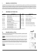
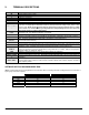
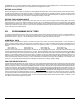
V. TERMINAL DESCRIPTIONS TERMINAL R1 R T T1 EARTH AC BELL + & BELL DATA COM POS SMOKE+ COM AUX + ZONE 8 COM ZONE 7 ZONE 6 - ZONE 1 AUX 1-AUX 4 DESCRIPTION House Telephone Ring (Grey). Telephone Ring (Red). Telephone Tip (Green). House Telephone Tip (Brown). Earth Ground. Connect to a cold water pipe or a 6 to 10 foot driven rod. AC input. Connect to a 16.5V 40 or 50 VA Class ll U.L. approved transformer.
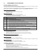
VI. PROGRAMMING THE LED KEYPADS KEYPAD ADDRESS AND PARTITION This section describes how to program the address and partition of each keypad as well as the options that are available. The address of the keypad is important because this is how the panel supervises the keypads. The factory default for the Master code is [1]-[2]-[3]-[4] when using a 4-digit code or [1]-[2]-[3]-[4]-[5]-[6] for a 6-digit code.
ASSIGNING AUTHORITY LEVEL: • • • Enter [r]-[6]-[master code]. The "Ready" LED will flash. Enter the 2 digit user number. The "Ready" LED will illuminate steady and the "Instant" LED will flash. Refer to the chart below for the description of each LED. Turn the LED on for the features that you desire.
the [MEDICAL] key. To review the data in a location, repeat the above procedure, pressing [r] without any numeric data entry. Each time [r] is pressed, the programming data of the next segment will be displayed for review. EXITING A LOCATION After the last segment of a location is programmed, pressing [r] will exit that location, turn the "Ready" LED off and the "Armed" LED on. The [r] must be pressed or the data will not be saved. To exit before the last segment, press [#].
PROGRAMMING EXAMPLE FIGURE1 (Numerical Data) Zone 1 LED = 1 Zone 4 LED = 8 } Data = 9 Zone 2 LED = 2 Zone 7 LED = 64 } Data = 66 To change data in a segment, enter the data followed by [ ] Enters the previous programming “location”. Pressing [#] will exit a location without changing the data in the current segment. Returns to the “location” just programmed. Advances to the next programming “location”.
IX. LOADING FACTORY DEFAULTS To load the factory defaults, enter the program mode using the procedure on page 8, then type [9]-[1]-[0]-[#]. The keypad will beep 3 times indicating that the loading is in progress. The loading takes about 6 seconds. X. ENROLLING MODULES AND KEYPADS For supervision purposes, the NX-8V2 has the ability to automatically find and store in its memory, the presence of all keypads, zone expanders, wireless receivers, and any other module connected to the data terminal.
L 3 DIAL ATTEMPTS/BACKUP CONTROL FOR PHONE 1 2 ........... numerical Segment 1- Dial attempts: Location 3, Segment 1 is used to enter the number of dial attempts (1 to 15 Attempts) the communicator will make to Phone 1 before ending the notification process. Factory default is "8" and the communicator will make eight (8) attempts to the first number.
L 8 COMMUNICATOR FORMAT FOR PHONE 2 1............. numerical Location 8 contains the communicator format used to transmit to the receiver connected to Phone 2. Consult the instruction manual for your central station receiver to determine which format is compatible, and select from Table XII-1 COMMUNICATOR FORMAT SELECTIONS on page 11. If you require a format other than those listed, review the override options described in Location 18 to build the appropriate format.
13 ACCOUNT CODE FOR PHONE 3 6 ............ numerical The account code sent when Phone 3 is dialed is programmed in location 13. Program a A10" in the segment immediately after the last digit of the account code. If the account code is 6 digits long, program all 6 segments. If location 6 is left unprogrammed, account code 1 will be used when the Phone 3 is dialed. 14 COMMUNICATOR FORMAT FOR PHONE 3 1 ............
18 CUSTOM COMMUNICATOR FORMAT (See loc 2, 8, &14) Segment 1: Segment 2: 1 = On for 1800hz transmit; Off for 1900hz. 1 = On for pager format (no handshake required). 2 = On for 2300hz handshake; Off for 1400hz. 2 = On for 1400/2300 handshake. 3 = On for cksum parity; Off for double round parity. 3 = Reserved 4 = On for 2 digit event code; Off for 1 digit event code. 4 = Reserved. 5 = Reserved. 5 = On for Contact ID. 6 = Reserved. 6 = On for SIA. 7 = On for 20 p.p.s.; Off for 10 or 40 p.p.s.
Segment 2: 1 = On enables the LED Extinguish feature. 2 = On enables the Require Code for Bypassing feature. 3 = On enables the Zone Bypassed Sounder Alert feature. 4 = On enables the AC Power/Low Battery Sounder Alert feature. 5 = On enables Bypass toggle. 6 = On enables Silent Auto Arm. 7 = On enables the Automatic Instant feature. 8 = On enables Instant mode toggle. (Applies to NX-1208E / NX-1248E keypads) Segment 3: 1 = On enables Opening and Closing reports. 2 = On enables Zone Bypass reporting.
DATA 11 12 13 14 15 16 17 18 19 20 21 22 23 24 25 26 27 28 29 30 DESCRIPTION OF DEFAULT ZONE TYPES KEYSWITCH ZONE - This zone type will arm and disarm the partition or partitions of the control panel that it resides in each time the zone is shorted. Keyswitch arming will report as user #99. INTERIOR FOLLOWER WITH "CROSS ZONE" ENABLED - This zone will be instant when the system is armed and no entry or exit delay is being timed. It is delayed during entry and exit delay times.
Segments 1 - 8: 1 = Partition 1 2 = Partition 2 3 = Partition 3 4 = Partition 4 5 = Partition 5 6 = Partition 6 7 = Partition 7 8 = Partition 8 L 27 ZONES 9-16 ZONE TYPE 8 ............ numerical Location 27 contains the Zone Type for zones 9 -16. Segment 1 is for zone 9; Segment 8 is for zone 16. Default Zone Types are found in the table on page 16. To customize a Zone Type, see page 28. 28 PARTITION SELECT, ZONES 9-16 8 ............
36 PARTITION SELECT, ZONES 41-48 8............. feature select Location 36 is used to select the partition or partitions that zones 41-48 reside in. A zone may reside in any combination of the 8 partitions. If a burglary zone resides in more than 1 partition it will only be active when all partitions are armed. A zone that resides in more than 1 partition will be reported to its lowest partition. Location 36 has 8 segments. Segment 1 corresponds to zone 41 and Segment 8 corresponds to zone 48.
Segment 6: 1 = Enable 2 wire smoke. 2 = Reserved. 3 = Enable for Zone Activity in Hours (not Days) 4 = Enable Daylight Savings Time (DST) 5 = Reserved 6 = On to disable Clean Me report (Default is OFF) 7 = On to disable Start/End Test report (Default is OFF) 8 = On enables Auto LED Extinguish (Default is OFF) Segment 7: Reserved L 38 SWINGER SHUTDOWN COUNT 1 ............ numerical Location 38 contains the number of trips during an arming cycle that the NX-8V2 will allow before bypassing a zone.
L 42 GO TO PROGRAM CODE 6............. numerical Location 42 contains the "Go To Program Code". This location contains either a 4 or 6-digit code. If the 6-digit code option is enabled in Location 41, THIS CODE MUST CONTAIN SIX (6) DIGITS. If this option is not enabled in location 41, the last 2 segments (digits) will be ignored. With the NX-8V2 disarmed, the "Go To Program Code" can be used to enter the Program Mode. 43 GO TO PROGRAM CODE PARTITION & AUTHORIZATION 2.............
48 Segment 1: Segment 2: AUXILIARY OUTPUT 2, EVENT & TIME 2 ............ numerical Use Table XIII-1 to select the event that will activate Auxiliary Output 2. Program the timing from 0-255 (minutes or seconds, depending on data programmed in Segment 2, Location 46). Programming a "0" makes the output follow the event. 49 Segment 1: Segment 2: AUXILIARY OUTPUT 3, EVENT & TIME 2 ............ numerical Use Table XIII-1 to select the event that will activate Auxiliary Output 3.
54 DAYS OF WEEK EACH PARTITION IS OPEN 8............. feature select Location 54 selects which days of the week each partition is open. On these days, Aarm only after close window@ codes will be able to arm and disarm during open window. NOTE: If any partition is not programmed to be opened and is programmed to Auto-Arm (Location 55), the NX-8V2 will try to arm every 45 minutes for the duration of the closed period unless Auto Retry is disabled in location 55.
SLOW COMMUNICATOR FORMAT CODES 61 SENSOR MISSING COMMUNICATOR CODE 8 ............ numerical Location 61 contains the event code for a zone "Sensor Missing" for a 4+2 format. Refer to the box on page 23. Segment 1 = Partition 1 Segment 3 = Partition 3 Segment 5 = Partition 5 Segment 7 = Partition 7 Segment 2 = Partition 2 Segment 4 = Partition 4 Segment 6 = Partition 6 Segment 8 = Partition 8 62 DURESS COMMUNICATOR CODE 2 ............
SLOW COMMUNICATOR FORMAT CODES 77 OPENING COMMUNICATOR CODE 8............. numerical Location 77 contains the digit of a 4+2 format if the "Opening Reporting" is enabled. Refer to the box on page 23. Segment 1 = Partition 1 Segment 3 = Partition 3 Segment 5 = Partition 5 Segment 7 = Partition 7 Segment 2 = Partition 2 Segment 4 = Partition 4 Segment 6 = Partition 6 Segment 8 = Partition 8 78 CLOSING COMMUNICATOR CODE 8.............
92 ACCOUNT CODE FOR PARTITION 3 6 ............ numerical The account code sent when partition 3 is reported is programmed in location 92. If location 92 is left unprogrammed (all A10") then the account code corresponding to the Phone number dialed will be used. If the account code is less than six digits, program a A10" in the segment immediately after the last digit of the account code. If the account code is 6 digits long program all 6 segments. 93 PARTITION 3 FEATURE & REPORTING SELECTIONS 5 ............
102 PARTITION 6 FEATURE & REPORTING SELECTIONS 5............. feature select Location 102 is used to enable certain features that can be accessed or are visible to the user from the keypad of the system. In addition, certain communicator reports are enabled in this location. Each of these features can be enabled by partition. This location contains 5 segments, with eight possible features per segment. Refer to Location 23 (page 15) for the feature selections.
LOCATIONS 110-169 ARE USED TO CHANGE THE ZONE TYPES (Configurations) AS LISTED IN THE TABLE ON PAGE 16. THESE LOCATIONS ARE CONSIDERED ADVANCED PROGRAMMING AND SHOULD ONLY BE CHANGED WITH A THOROUGH UNDERSTANDING OF THE OPERATION OF EACH BIT. 110 ZONE TYPE 1 ALARM EVENT CODE 1 ............ numerical Location 110 contains the event code sent for a Contact ID or SIA report. The desired event code should be chosen from the list on page 16. The zone ID will be that zone that is in alarm.
116 ZONE TYPE 4 ALARM EVENT CODE 1............. numerical Location 116 contains the event code sent for a Contact ID or SIA report. The desired event code should be chosen from the list on page 50. The zone ID will be that zone that is in alarm. If 4+2 format is being used, refer to Location 110 on page 28 for details. 117 ZONE TYPE 4 CHARACTERISTIC SELECT Use "Zone Type Characteristic Selections" described in Location 111, page 28 5............. feature select 118 ZONE TYPE 5 ALARM EVENT CODE 1..........
136 ZONE TYPE 14 ALARM EVENT CODE 1 ............ numerical Location 136 contains the event code sent for a Contact ID or SIA report. The desired event code should be chosen from the list on page 50. The zone ID will be that zone that is in alarm. If 4+2 format is being used, refer to Location 110 on page 28 for details. 137 ZONE TYPE 14 CHARACTERISTIC SELECT Use "Zone Type Characteristic Selections" described in Location 111, page 28 5 ............ feature select 138 ZONE TYPE 15 ALARM EVENT CODE 1 ......
156 ZONE TYPE 24 ALARM EVENT CODE 1............. numerical Location 156 contains the event code sent for a Contact ID or SIA report. The desired event code should be chosen from the list on page 50. The zone ID will be that zone that is in alarm. If 4+2 format is being used, refer to Location 110 on page 28 for details. 157 ZONE TYPE 24 CHARACTERISTIC SELECT Use "Zone Type Characteristic Selections" described in Location 111, page 28 5............. feature select 158 ZONE TYPE 25 ALARM EVENT CODE 1.......
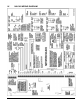
XIV. PROGRAMMING WORKSHEETS (Factory defaults for segments are in bold italics text and "Quick Start" locations are identified with the L symbol.
LOC 17 PG 14 18 15 L L L 19 20 21 15 15 15 L 22 15 L 23 15 L 24 16 L 25 17 DESCRIPTION DEFAULT PROGRAM DATA PHONE 3, SELECTING WHICH PARTITIONS REPORT TO PHONE 3 Segment 1 (Circle Numbers To Program) 1 = Partition 1 3 = Partition 3 5 = Partition 5 7 = Partition 7 2 = Partition 2 4 = Partition 4 6 = Partition 6 8 = Partition 8 FORMAT OVERRIDE Segment 1 (Circle Numbers To Program) Segment 2 (Circle Numbers To Program) 1 = ON - 1800hz transmit; OFF - 1900hz 1 = ON - pager format (no handshak
LOC 26 L 27 28 L 29 30 L 31 32 L 33 34 L 35 36 34 PG DESCRIPTION DEFAULT PROGRAM DATA 17 ZONES 1-8, PARTITION SELECTION (Segment 1=Zone 1 thru Segment 8=Zone 8) Segments 1 2 3 4 5 6 7 8 Partition 1 1 1 1 1 1 1 1 1 Partition 2 2 2 2 2 2 2 2 2 Partition 3 3 3 3 3 3 3 3 3 Partition 4 4 4 4 4 4 4 4 4 Partition 5 5 5 5 5 5 5 5 5 Partition 6 6 6 6 6 6 6 6 6 Partition 7 7 7 7 7 7 7 7 7 Partition 8 8 8 8 8 8 8 8 8 18 ZONES 9-16, ZONE TYPES 6-6-6-6-6-6-6-6 ________ 18 ZONES 9-16, PARTITION SELECTION (Seg
LOC 37 L L 38 PG 19 20 NX-8V2 Control DESCRIPTION DEFAULT PROGRAM DATA SIREN AND SYSTEM SUPERVISION Segment 1 (Circle Numbers To Program) 1 = Siren sounds for telephone line cut while armed. 2 = Siren sounds for telephone line cut while disarmed. 3 = Siren blast at arming. 4 = Siren blast at exit delay expiration. 5 = Siren blast at closing kissoff. 6 = Siren sounds during a cross-zone verification time. 7 = Siren sounds for a tamper.
L 39 LOC PG 20 L 40 20 41 20 L 42 43 21 21 44 45 21 21 L 36 DESCRIPTION DEFAULT KEYPAD SOUNDER Segment 1 (Circle numbers to program) 1 = Keypad sounds for Telephone Line Cut when in the Armed state. 2 = Keypad sounds for Telephone Line Cut when in the Disarmed state. 3 = Keypad sounds upon AC Power Failure. 4 = Keypad sounds upon Low Battery Detection. 5 = Keypad sounds during Cross Zone Trip Time. 6 = Keypad sounds for Tamper Alarm. 7 = Reserved.
LOC 46 L PG 21 47 21 48 22 49 22 50 22 51 22 52 22 53 22 54 23 55 23 DESCRIPTION DEFAULT AUXILIARY OUTPUTS 1-4 SPECIAL TIMING Segments 1 1 1 = Aux output timed in minutes. 2 2 = Aux output to latch. 3 3 = Aux output to stop timing upon user code entry. 4 4 = Aux output to activate only between closing & opening time. 5 5 = Aux output to activate only between opening & closing time. 6 6 = Invert auxiliary output (0 Volts going to 12V when activated).
COMMUNICATOR CODES FOR SLOW SPEED FORMATS ONLY The digit programmed in each of the following locations will be sent as the upper HEX digit in place of the alarm event code. The zone ID or user ID will always be reported as the lower HEX digit (1-F). For example, if the zone ID or user ID is 15, the 4+2 lower digit will be “F”. (Refer to Appendix 4 on page 53.) If Segments 2-8 are left as “0” (unprogrammed), they will follow the Segment 1 selection.
LOC 64 65 66 67 68 69 70 71 72 73 74 75 76 77 78 79 80 81 82 83 84-87 88 89 90 PG 24 24 24 24 24 24 24 24 24 24 24 24 24 25 DESCRIPTION AUXILIARY 2 KEYPAD PANIC KEYPAD MULTIPLE CODE ENTRY TAMPER BOX TAMPER / BOX TAMPER RESTORE AC FAIL / AC RESTORE LOW BATTERY / LOW BATTERY RESTORE POWER SHORT / POWER SHORT RESTORE BELL TAMPER / BELL TAMPER RESTORE TELEPHONE LINE CUT / LINE CUT RESTORE GROUND FAULT / GROUND FAULT RESTORE EXPANDER TROUBLE / EXP TROUBLE RESTORE 25 25 25 25 25 25 25 25 25 25 FAILURE TO C
LOC 91 92 93 26 26 94 26 95 96 26 26 97 26 98 40 PG 25 26 DESCRIPTION DEFAULT PARTITION 2 ENTRY/EXIT TIMERS Segment 1: Entry Time 1 0 Segment 2: Exit Time 1 0 Segment 3: Entry Time 2 0 Segment 4: Exit Time 2 0 Segment 5 & 6 RESERVED PARTITION 3, ACCOUNT CODE 10-10-10-10-10-10 PARTITION 3, FEATURE AND REPORTING SELECTION Segment 1 1 = Quick Arm 5 = Audible Panic 2 = Re-Exit 6 = Auxiliary 1 3 = Auto Bypass 7 = Auxiliary 2 4 = Silent Panic 8 = Multi Keypress Tamper Segment 2 1 = LED extinguish ena
LOC 99 PG 26 100 26 101 102 26 27 103 27 104 105 27 27 DESCRIPTION DEFAULT PARTITION 5, FEATURE AND REPORTING SELECTION Segment 1 1 = Quick Arm 5 = Audible Panic 2 = Re-Exit 6 = Auxiliary 1 3 = Auto Bypass 7 = Auxiliary 2 4 = Silent Panic 8 = Multi Keypress Tamper Segment 2 1 = LED extinguish enable 5 = Enables bypass toggle 2 = Require user code for bypassing zones 6 = Enables silent auto arm 3 = Bypass sounder alert 7 = Enables auto instant 4 = AC power/low battery sounder alert 8 = Reserved Seg
LOC 105 PG 27 106 27 107 108 27 27 109 27 110 111 28 28 42 DESCRIPTION DEFAULT PROGRAMMING DATA Segment 2 1 = LED extinguish enable 5 = Enables bypass toggle 2 = Require user code for bypassing zones 6 = Enables silent auto arm 3 = Bypass sounder alert 7 = Enables auto instant 4 = AC power/low battery sounder alert 8 = Reserved Segment 3 1 = Open/Close 5 = Tamper 2 = Bypass 6 = Cancel 3 = Restore 7 = Recent Closing 4 = Trouble 8 = Exit Error Segment 4 1 =Late to Close / Early to Open 2-8 = Reserv
LOC 111 PG 28 DESCRIPTION Segment 3 1 = Fast Loop Response. 2 = Double End of Line Tamper zone. 3 = Trouble zone (Day zone). 4 = Cross Zone. Segment 4 1 = Zone Activity Monitor. 2 = End of Line Resistor Defeat. 3 = Zone acts as Request to Exit input. Segment 5 RESERVED DEFAULT 5= 6= 7= 8= PROGRAMMING DATA Dialer Delay zone. Swinger zone. Restore reporting. Listen-In. 4 = Zone acts as access entry point (Do not enable this segment unless configured with Access Control module) 5 -8 = Reserved.
LOC 156 157 158 159 160 161 162 163 164 165 166 167 168 169 170-205 206 44 DESCRIPTION DEFAULT ZONE TYPE 24 ALARM EVENT CODE 22 ZONE TYPE 24 CHARACTERISTIC SELECT 1-13-378 ZONE TYPE 25 ALARM EVENT CODE 14 ZONE TYPE 25 CHARACTERISTIC SELECT 248-45-0-0-0 ZONE TYPE 26 ALARM EVENT CODE 5 ZONE TYPE 26 CHARACTERISTIC SELECT 467-125-5678-0-0 ZONE TYPE 27 ALARM EVENT CODE 5 ZONE TYPE 27 CHARACTERISTIC SELECT 457-1257-5678-0-0 ZONE TYPE 28 ALARM EVENT CODE 7 ZONE TYPE 28 CHARACTERISTIC SELECT 6-12457-5678-0-0 ZONE
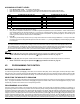
ZONE WORKSHEET 1 25 2 26 3 27 4 28 5 29 6 30 7 31 8 32 9 33 10 34 11 35 12 36 13 37 14 38 15 39 16 40 17 41 18 42 19 43 20 44 21 45 22 46 23 47 24 48 NX-8V2 Control 45
XV. GLOSSARY Abort If enabled, the NX-8V2 will wait the programmed number of seconds in location 40 prior to sending an alarm. During this delay time, the “Cancel” LED will flash. To abort the report, type in a code and press the Cancel key. The LED will extinguish. If the report is not aborted within the allotted time, the LED will extinguish when the report is sent. ADialer Delay@ must be enabled in the ACharacteristic Select@ of locations 110-169.
Dual / Split / Multiple Reports The NX-8V2 can send communication reports to three different phone numbers for dual, split or multiple reports selectable by event or partition. (Loc 4, 10, & 16, pg 12, 13, 14) Duress Code If a duress code is programmed the NX-8V2 will send a duress signal whenever the panel is armed or disarmed with this code. If open/close reports are sent, the user code will be 254.
Keyswitch Arm/Disarm Any zone on the NX-8V2 can be programmed as a keyswitch zone. If this is done, a momentary short on this zone will arm/disarm the control. If opening/closing reports are sent, the user code will be 99. (See "Default Zone Types", pg 16) LED Extinguish This feature will extinguish all LEDs on the keypad, except the "Power" LED, after 60 seconds without a keypress. Pressing any numeric key will illuminate all LED=s.
Tone Sniff Answering Machine Defeat If enabled, only one call is required to defeat the answering machine. To use this feature you must have a Hayes 1200 Smart Modem. From the computer, call the panel as normal. When the answering machine answers, the panel will hear the tones from the modem and seize the phone line for a download. (Loc 21, pg 15) This is not recommended for commercial applications.
XVI. APPENDIX 1 REPORTING FIXED CODES IN CONTACT ID AND SIA The table below lists the event codes sent for the following reports (if enabled) when using CONTACT ID or SIA formats. REPORT CONTACT ID SIA AC FAIL (device number) ...........................................................301 .................................................. AT AC RESTORE (device number) .................................................301 .................................................. AR AUTOTEST ....................
XVII. APPENDIX 2 REPORTING ZONE CODES IN SIA OR CONTACT ID The NX-8V2 has the ability to report SIA level 1 transmissions to either or both phone numbers. Each report in SIA consists of an Event Code and a Zone or User ID. The Zone ID will be the zone number that is in alarm. The event code will come from the chart below and be programmed in the zone type event code. Programmed Event Code SIA Code Description 0....................................................... HA..................................
XVIII. APPENDIX 3 EXPANDER NUMBERS FOR REPORTING EXPANDER TROUBLE The tables below list the device numbers that will be reported for trouble conditions.
XIX. APPENDIX 4 USER ID OR ZONE ID HEX DIGIT FOR 4+2 FORMATS The following appendix applies only to slow formats (locations 56- 83 lower digit). The digit programmed in the locations will be sent as the upper HEX digit in place of the alarm event code. The zone ID or user ID will always be reported as the lower HEX digit (1F) as shown in the chart below. For example, if the zone ID or user ID is 15, the 4+2 lower digit will be “F”. Use the chart shown below for convenience.
XX. LOCAL TELEPHONE COMPANY INTERFACE INFORMATION TELEPHONE CONNECTION REQUIREMENTS Except for telephone company provided ringers, all connections to the telephone network shall be made through standard plugs and standard telephone company provided jacks or equivalent in such a manner as to allow for immediate disconnection of the terminal equipment.
XXII.
XXIII.
MINIMUM SYSTEM CONFIGURATIONS FOR UL INSTALLATIONS • • • • • • • (Residential Fire, Residential Burglary, Commercial Burglary) The NetworX NX-8V2 panel is necessary to initiate Residential and Commercial installations. At least one compatible keypad is needed for all applications. At least one bell fixture is required for all applications, except Grade C Central Station. For Grade A Local, the AD10-12 bell and Grade A bell housing shall be used. Commercial UL applications require #NX-003-C metal enclosure.
ANSI / SIA CP-01 REQUIREMENTS 1 3 8 8 40 Dialer Delay Dialer Delay 3/7 3/8 3 23 23 40 Swinger Shutdown Count Default Changes (from prior versions): Call Waiting Cancel Power Up Delay Exit Error Recent Closing Must be programmed as part of the phone number Fire Alarm Verification Time Swinger Shutdown Disable Cross Zone Time Zone Type Characteristic 60 sec.
SYSTEM NOTES
XXV. SPECIFICATIONS OPERATING POWER AUXILIARY POWER w/25 VA Transformer w/40 or 50 VA Transformer w/NX-320E Power Supply 16.