EPM 5200, 5300, 5350 DIGITAL MULTIFUNCTION POWER MONITORS Instruction Manual GEK-106557A Copyright © 2004 GE Multilin g NORTH AMERICA 215 Anderson Avenue, Markham, Ontario, L6E 1B3 Canada Tel: (905) 294-6222 Fax: (905) 201-2098 E-mail: info.pm@indsys.ge.com Internet: http://www.GEindustrial.
TABLE OF CONTENTS CHAPTER 1: AC POWER MEASUREMENT .............1 1.1: Single Phase System................1 1.2: Three-Phase System ................2 1.3: Consumption, Demand and Poor Power Factor ....................3 1.4: Waveform and Harmonics ........4 CHAPTER 2: MECHANICAL INSTALLATION ...............5 CHAPTER 3: ELECTRICAL INSTALLATION ...............7 3.1: Current Circuit...........................7 3.2: CT Connection ..........................7 3.3: Voltage Circuit...........................8 3.
CHAPTER 10: PROGRAMMING GROUP 1: VOLTAGE, AMP AND WATT SCALE SETTINGS.........55 10.1: Group 1, Function 0—Full Scale Voltage Settings, Scale Factor & Decimal Point Placement ...............................55 10.2: Group 1, Function 1— Amperage Full Scale...............58 10.3: Group 1, Function 2—Scale Selection and Decimal Placement for Watts................59 CHAPTER 11: PROGRAMMING GROUP 2: METER CALIBRATION .......63 11.1: Calibration Requirements .......63 11.
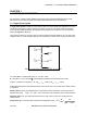
CHAPTER 1: AC POWER MEASUREMENT CHAPTER 1 AC POWER MEASUREMENT The economics of electric power distribution networking dictate several configurations of AC power transmission. The number of phases and voltage levels characterize these configurations. 1.1: Single Phase System A single phase system is a basic two-wire system used in low power distribution applications, such as residential communities or offices. Typically, the voltage is 120V AC.
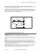
CHAPTER 1: AC POWER MEASUREMENT Reactive Power (VAR) Apparent Power (VA) Real Power (W) Figure 1.2: Relationship between apparent, real and reactive power Ideal power distribution should have a PF of 1. This condition can be met only if no reactive power loads exist. In real life applications, many loads are inductive loads. Often, corrective capacitors are installed to correct Poor Power Factor (see Section 1.3). 1.
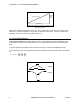
CHAPTER 1: AC POWER MEASUREMENT Voltages between the phases vary depending on loading factors and the quality of distribution transformers. The three-phase system is distributed in different voltage levels: 208V AC, 480V AC, 2400V AC, 4160V AC, 6900V AC, 13800V AC, and so on. Power measurement in a poly phase system is governed by Blondel's Theorem. Blondel’s Theorem states that in a power distribution network which has N conductors, the number of measurement elements required to determine power is N-1.
CHAPTER 1: AC POWER MEASUREMENT 1.4: Waveform and Harmonics Ideal power distribution has sinusoidal waveforms on voltages and currents. In real-life applications, where inverters, computers, and motor controls are used, distorted waveforms are generated. These distortions consist of harmonics of the fundamental frequency.
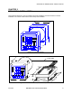
CHAPTER 2: MECHANICAL INSTALLATION CHAPTER 2 MECHANICAL INSTALLATION These diagrams display the various possible mechanical installations and Communication Converter installation. The various models use the same hookup and installation. 4.50 SQ. AC VO LTS M AX A B C A B C N N N B C A M IN LM 1 M AX THD AC AM PS A B C N K PO W ER KVAH M AX/M IN LIM ITS KW H VOLTS FREQ AM PS POW ER 2.0 PF KW KVA KVAR 3.0 PHASE NEXT 4.375 0.890 SQ. Diagram 2.1: Standard installation 3 FOOT CABLE 3.
CHAPTER 2: MECHANICAL INSTALLATION SIDE VIEW (4) 8-32 SCREWS FIRST PUT (16) PIN CONNECTOR TOGETHER. 0.80 (2) 8-32 SCREWS WILL LINE UP WITH 2 PEMS ON THE BACK PLATE. RECOMMENDED CUTOUT 0.198 DIA. 1.6875 4.0 DIA. 3.375 1.6875 3.375 BACK VIEW Diagram 2.3: Standard cutout W Port Diagram 2.4: Optional Communication Converter or DC Output Module Installation * Recommended wire gauge is 20 AWG for DC Output or RS-485 options.
CHAPTER 3: ELECTRICAL INSTALLATION CHAPTER 3 ELECTRICAL INSTALLATION 3.1: Connecting the Current Circuit Install the wiring for the current at 600V AC insulation as a minimum. The cable connector should be rated for 6 Amps or greater and have a cross-sectional area of 16 AWG minimum. Mount the current transformers (CTs) as close as possible to the meter for best accuracy. The following table illustrates the maximum recommended distances for various CT sizes, assuming the connection is via 16 AWG cable.
CHAPTER 3: ELECTRICAL INSTALLATION OPTION 2: ISOLATING A CT CONNECTION REVERSAL USING VOLTAGE READINGS ! ! Remove potential connections to terminals 6 and 7. Observe the KW reading. It should be positive. If negative, reverse the CT wires on terminals 8 and 9. Connect terminal number 6 potential. If KW decreases to about zero, reverse CT wires on terminals 10 and 11. Connect terminal number 7 potential. If KW is one-third of expected reading, reverse CT wires to terminals 12 and 13. 3.
CHAPTER 3: ELECTRICAL INSTALLATION • The meter and terminal module DSP3 are factory calibrated together; the serial numbers are matched on both. The DSP3 input module and the meter base MUST MATCH! • Mismatching of the meter and DSP3 input module will cause inaccurate readings because calibration ratios are stored in the meter’s memory, not in the DSP3 input module. LIST OF CONNECTION DIAGRAMS NOTE: See phase reversal if a message of CBA appears after installation.
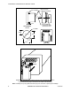
CHAPTER 3: ELECTRICAL INSTALLATION A LINE B BACK VIEW C 7 8 10 9 11 12 13 6 PORT 5 4 3 2 L1 + POWER LOAD 1L - II. Three-Phase, Three-Wire Open Delta with two CTs and two PTs Note: Remember to make sure Open Delta bit is programmed in the meter (see section 9.4). A LINE B BACK VIEW C 78 9 10 11 12 13 6 5 PORT 4 3 LOAD + 2 L1 - 1L POWER III.
CHAPTER 3: ELECTRICAL INSTALLATION N LINE A B C BACK VIEW 7 8 10 9 11 12 13 6 PORT 5 4 3 CONTROL + 2 L1 - 1 L POWER LOAD IV. Three-Phase Four-Wire Wye with Direct Voltage and CTs LINE N A B BACK VIEW C 7 8 9 10 11 12 13 6 5 PORT 4 3 + POWER LOAD - 2 L1 1 L V.
CHAPTER 3: ELECTRICAL INSTALLATION The EPM 5300P-S The EPM 5300P -S is essentially the 5300P, where through the Programming Mode calculations are changed to reflect either Single Phase or Dual Phase readings. Single Phase—The connection MUST be identical to Diagram VI. Dual Phase—The connection MUST be identical to Diagram VII. Program 1 for Single Phase or 2 for Dual Phase in GROUP 0, FUNCTION 7 to remove Three-Phase indicators from view.
CHAPTER 3: ELECTRICAL INSTALLATION LINE BACK VIEW B A 7 8 9 10 11 12 13 6 PORT 5 4 3 POWER LOAD + 2 L1 - 1 L VII. Dual-Phase with CTs and PTs LINE N A B BACK VIEW C 7 8 9 10 11 12 13 6 5 PORT 4 3 LOAD CONTROL POWER + 2 L1 - 1 L VIII. Three-Phase Four-Wire WYE with 2.5 Element Note: The 2.5 element option must be custom configured from the factory. You must pre-order this configuration.
CHAPTER 3: ELECTRICAL INSTALLATION 3.7: Relay, Protection and Pulse Output (This section applies only to the -NL or -NL2 Relay Option.) EPM 5300P RELAY OVERVIEW The EPM 5300P offers dry contact relay output capability. The EPM 5200P only offers KYZ pulse outputs and cannot be configured to trip contacts on events. FAIL-SAFE MODE: The EPM 5300P -NL option gives the user an adjustable tripping bandwidth.
CHAPTER 3: ELECTRICAL INSTALLATION 20 N .O . 21 N .C . 22 COM 23 N .O . 24 N .C . 25 COM 26 K 27 Y 28 Z A LA R M #1 A LA R M #2 P U LS E O U TP U T Figure 3.1: Close-up of the Relay and KYZ pulse output on the rear panel. Note: The relays shown in the figure above are in the NOT energized state.
CHAPTER 3: ELECTRICAL INSTALLATION Note: Unless otherwise specified, standard KYZ setup for Pulse Output 0 is positive Watt Hour, Pulse Output 1 is negative Watt-Hour, and Pulse Output 2 is VA-hour. See table below for standard rate. Note: With Option R (available only with the EPM 5200P) the setup for Pulse Output 0 is positive Watt-Hour, Pulse output 1 is positive VAR-hour, and Pulse output 2 is negative VAR-hour.
CHAPTER 4: COMMUNICATION INSTALLATION CHAPTER 4 COMMUNICATION INSTALLATION 4.1: RS-232C (This section applies to the RS-232C or RS-485.) All EPM 5300P and 5200P instruments can be equipped with RS-232C or RS-485 communication. RS-232C communication links a single instrument with a computer or device such as an RTU or PLC. Its capability is up to 100 feet. A standard 9-pin female serial port connector mounts on the instrument for direct connection to a computer with a 9-pin cable.
CHAPTER 4: COMMUNICATION INSTALLATION RS-485 Hookup Diagram (2 wire) Half Duplex 5300P Instruments (rear view) RS-485 Communications Port Model#SF485DB RT RT RS-485 UNICOM 2500 (Bottom View Shown) RS-232 PC (+) (-) Figure 4.
CHAPTER 4: COMMUNICATION INSTALLATION RS-485 Hookup Diagram (2 wire) Half Duplex (Closed Loop) 5300P Instruments (rear view) RS-485 RS-232 RS-485 Communications Port Model #SF485DB UNICOM 2500 (Bottom View Shown) Figure 4.
CHAPTER 4: COMMUNICATION INSTALLATION RS-485 Hookup Diagram (2 wire) Half Duplex: Detail View RS-485 Communications Port RS-485 Communications Port Model# SF485DB Model# SF485DB G R+ T+ R- T- G R+ T+ R- T- RT RS-485 RS-232 (-) (+) UNICOM 2500 (Bottom View Shown) TRT+ R+ Gnd Figure 4.
CHAPTER 4: COMMUNICATION INSTALLATION RS-485 Hookup Diagram (4 wire) Full Duplex 5300P Instruments (rear view) RS-485 Communications Port Model#SF485DB Note: This does not represent a twisted pair. It shows the cross-over from R to T between the Unicom and the rest of the bus. RS-485 UNICOM 2500 (Bottom View Shown) RS-232 PC R+ R- T+ T- Figure 4.
CHAPTER 4: COMMUNICATION INSTALLATION RS-485 Hookup Diagram (4 wire) Full Duplex: Detail View Note: This does not represent a twisted pair. It shows the cross-over from R to T between the Unicom and the rest of the bus.
CHAPTER 4: COMMUNICATION INSTALLATION 4.3: Network of Instruments and Long Distance Communication The RS-485 Transceiver is required for a large network of instruments. • In a two-wire connection, a maximum of 900 instruments can be included in the same network (Figure 4.7) • In a four-wire connection, a maximum of 3600 instruments can be included in the same network (Figure 4.8).
CHAPTER 4: COMMUNICATION INSTALLATION YOU MAY WANT TO USE A MODEM MANAGER RS485-RS232 CONVERTER When speaking to most RS-485 or RS-232C based devices, the remote modem must be programmed for the communication to work. This task is often quite complicated because modems are quirky when talking to remote devices. To make this task easier, EIG has designed a Modem Manager RS-485 to RS-232C converter. This device automatically programs the modem to the proper configuration.
CHAPTER 4: COMMUNICATION INSTALLATION Debugging Communication Problems If you experience NO communication, check these conditions: • • • • Is the Baud Rate set correctly (see Part II: Programming Section)? Is the Meter Address set correctly (see Part II: Programming Section)? Is the correct protocol set? Modbus, DNP 3.0? Set the meter for the appropriate protocol for the internal software.
CHAPTER 4: COMMUNICATION INSTALLATION 26 EPM 5000 series Advanced Power Meters GE Multilin
CHAPTER 5: OVERVIEW CHAPTER 5 OVERVIEW The EPM 5300P displays 17 instantaneous electrical parameters. Values for each parameter are accessed through the keypad on the meter's front panel (see Figure 5.1). The EPM 5200P accesses information in the same manner as the 5300P. The key strokes for each model are identical.
CHAPTER 5: OVERVIEW 5.1: Accessing the Power Functions AC VOLTS MAX MIN N N N B C A LM1 LM2 AC VOLTS MAX MIN A B C A B C A B C A B C N N N B C A LM1 LM2 AC AMPS AC AMPS A B C N A B C N KVAH MAX/MIN LIMITS FREQ KWH VOLTS AMPS POWER POWER POWER PF KW KVA KVAR PF KW KVA KVAR KVAH PHASE MAX/MIN NEXT LIMITS KWH VOLTS AMPS FREQ PHASE POWER NEXT Step 1: a. Press POWER to select the power category. Step 2: a. Press PHASE/NEXT for the desired power function.
CHAPTER 5: OVERVIEW To access %THD: AC VOLTS MAX MIN A B C A B C N N N B C A LM1 AC VOLTS MAX MIN A B C A B C N N N B C A LM1 LM2 THD K AC AMPS A B C N LM2 THD K AC AMPS A B C N POWER KVAH FREQ KWH POWER PF KW KVA KVAR KVAH VOLTS LIMITS THD MAX/MIN AMPS THD POWER PF KW KVA KVAR FREQ KWH PHASE NEXT MAX/MIN LIMITS Step 1: a. To access %THD values for a voltage or current phase press VOLTS/THD (or AMPS/THD) twice.
CHAPTER 5: OVERVIEW 5.5: Accessing Max/Min Values Max/min values represent the highest and lowest average demand over a user programmable time period known as the Integration Interval. The readings are calculated using a rolling average technique. Each second, a new reading is used to calculate the max/min; the last reading of the interval is dropped off. The highest max during an averaging period is stored until the user resets the max/min. This is similar to amp demand meters.
CHAPTER 5: OVERVIEW UNPROTECTED RESET To reset the min of Amps A: AC VOLTS MAX MIN N N N B C A LM1 LM2 AC VOLTS MAX MIN A B C A B C N N N B C A LM1 LM2 AC AMPS KVAH MAX/MIN LIMITS VOLTS AMPS POWER N N N B C A LM2 AC AMPS A B C N A B C N POWER POWER POWER PF KW KVA KVAR PF KW KVA KVAR PF KW KVA KVAR FREQ KWH A B C A B C LM1 AC AMPS A B C N AC VOLTS MAX MIN A B C A B C PHASE MAX/MIN NEXT LIMITS Step 1: a.
CHAPTER 5: OVERVIEW 5.
CHAPTER 5: OVERVIEW AC VOLTS MAX MIN A B C A B C a. To access the set limit, press MAX/MIN/LIMITS N N N B C A LM1 LM2 AC AMPS • • A B C N POWER VOLTS LIMITS PF KW KVA KVAR FREQ KWH KVAH MAX/MIN AMPS 3 times for LM1 4 times for LM2 POWER PHASE NEXT 5.9: Voltage Phase Reversal and Imbalance In a three-phase power distribution system, normal phase shift between each line is 120°. If the EPM 5300P detects an abnormality, it displays a message of PH. The EPM 5200P does not have this feature.
CHAPTER 5: OVERVIEW 5.10: Access Modes The following access commands allow the user to perform specific operations. ACCESS COMMANDS 1 2 3 4 OPERATION Print Operating Data Print Programming Data Enter Programming Mode (see Programming Section) Firmware Version/LED Test Note: Print commands 1 and 2 are only available if enabled in the programming mode; they are not recommended when using the multimeter connection RS-485. 5.
CHAPTER 5: OVERVIEW 5.12: Print Programming Data This function sends the programming data (or the meter setup) to a serial printer for verification and quick reference.
CHAPTER 5: OVERVIEW AC VOLTS MAX MIN N N N B C A LM1 LM2 AC VOLTS MAX MIN A B C A B C A B C A B C N N N B C A LM1 LM2 AC AMPS AC AMPS A B C N A B C N KVAH MAX/MIN LIMITS KWH VOLTS AMPS FREQ POWER POWER POWER PF KW KVA KVAR PF KW KVA KVAR KVAH PHASE MAX/MIN NEXT LIMITS Step 3: a. Press PHASE/NEXT for the LED test. ! All segments and annunciators glow. 36 KWH VOLTS AMPS FREQ POWER PHASE NEXT Step 4: a.
CHAPTER 6: PROGRAMMAING OVERVIEW CHAPTER 6 PROGRAMMING OVERVIEW 6:1: General Procedure Programming tasks are arranged into nine major GROUPS. Within each GROUP are the specific meter FUNCTIONS. Outlined is the general approach to alter programming mode values. 1. Enter the Programming Mode. 2. Select the desired GROUP. 3. Once the desired GROUP is selected, select a FUNCTION within the GROUP.
CHAPTER 6: PROGRAMMING OVERVIEW 6.3: Programming Mode Data Entry The EPM 5300P and EPM 5200P programming mode utilizes only three out of the five-keypad buttons: the MAX/MIN/LIMITS, VOLTS/THD, and AMPS/THD buttons. U SED FOR MAX/MIN VOLTS LIMITS U SED THD FOR P ASSWORD E NTRY AMPS THD POWER PHASE NEXT P ROGRAMMING Note: The EPM 5200P uses the same keypad strokes and methods. Although the keypad may look slightly different, the keys match the EPM 5300P exactly.
CHAPTER 7: EPM 5200P CHAPTER 7 EPM 5200P The EPM 5200P is similar to the regular EPM 5300P with the following exceptions: 1. The size of the display digits is smaller (0.300” instead of 0.560”). 2. The following features are not available: • The energy readings: VA/H, VAR/H. • The limits: Lim1 and Lim2, and dry contact relay outputs. • The harmonics readings: %THD and K-factor. 3. The layout of the keypad is slightly different (although the keys have exactly the same functions).
CHAPTER 7: EPM 5200P EPM 5300P vs. EPM 5200P vs. EPM 5350P Feature Voltage 3-Phase Voltage Accuracy Current 3-Phase and Neutral Current Accuracy Watts, VARS, VA, PF Watts Accuracy Frequency Watt/HR VAR/HR (Optional) VA/HR Harmonics to 31st Order Feature Max/Min Demand Limits Relays and Logic Pulse Outputs Digital Communication Modbus RTU Modbus ASCII DNP Protocol Modbus Plus Capability Analog Outputs Modbus TCP Ethernet 40 5300P 5200P 5350P ! 0.2% ! ! 0.3% ! ! 0.2% ! 0.2% ! 0.3% ! 0.2% ! 0.
CHAPTER 8: ENTERING PROGRAMMING MODE CHAPTER 8 ENTERING PROGRAMMING MODE 8.1: Checksum Error—Protective Self-Checking Algorithms This checksum error is a protective self-checking wealth algorithm designed to alert the user when a procedure has not been correctly followed, ensuring that the meter does not display inaccurate readings. If the control power is interrupted while in Programming Mode or the user does not completely exit, the meter enters a checksum mode. The max LED flashes.
CHAPTER 8: ENTERING PROGRAMMING MODE NOTE: AUTO SCROLLING will automatically show all of the readings on the face of the meter except LIMITS. To enter Auto Scrolling mode, follow the above steps except use the numbers 666 as the password. To exit Auto Scrolling mode, use the same procedure as described above.
CHAPTER 9: PROGRAMMING GROUP 0 – GLOBAL METER SETUP CHAPTER 9 PROGRAMMING GROUP 0 – GLOBAL METER SETUP The Global Meter Setup includes FUNCTIONS 0 through 7 that control configuration and basic operation. FUNCTION 3 System Configuration contains Switch PACKS with various options, including Open Delta installation, communications or DC Output setup. Global Meter Setup is the section in which general features are programmed. FUNCTION NUMBER 0. 1. 2. 3. 4. 5. 6. 7. E.
CHAPTER 9: PROGRAMMING GROUP 0 – GLOBAL METER SETUP AC VOLTS MAX MIN N N N B C A LM1 AC VOLTS MAX MIN A B C A B C A B C A B C N N N B C A LM1 LM2 LM2 AC AMPS AC AMPS A B C N A B C N POWER KVAH FREQ KWH POWER PF KW KVA KVAR KVAH MAX/MIN LIMITS VOLTS AMPS POWER PF KW KVA KVAR FREQ KWH PHASE MAX/MIN NEXT LIMITS VOLTS AMPS POWER PHASE NEXT !Repeat this procedure until new Integration Interval is entered. Step 2: a. Press AMPS once to begin Data Entry Sequence.
CHAPTER 9: PROGRAMMING GROUP 0 – GLOBAL METER SETUP AC VOLTS MAX MIN A B C A B C N N N B C A LM1 LM2 AC AMPS AC VOLTS MAX MIN A B C A B C N N N B C A LM1 LM2 AC AMPS A B C N KVAH MAX/MIN LIMITS VOLTS POWER POWER PF KW KVA KVAR PF KW KVA KVAR FREQ KWH AMPS POWER A B C N KVAH PHASE MAX/MIN NEXT LIMITS Step 3: a. Press AMPS once to begin Data Entry Sequence. ! The previous value shifts to middle display and four dashes appear in lower display. b. Press VOLTS for desired number.
CHAPTER 9: PROGRAMMING GROUP 0 – GLOBAL METER SETUP AC VOLTS MAX MIN N N N B C A LM1 LM2 AC VOLTS MAX MIN A B C A B C A B C A B C N N N B C A LM1 LM2 AC AMPS AC AMPS A B C N KVAH MAX/MIN LIMITS FREQ KWH VOLTS AMPS POWER A B C N POWER POWER PF KW KVA KVAR PF KW KVA KVAR KVAH PHASE MAX/MIN NEXT LIMITS Step 3: a. Press AMPS to begin Data Entry Sequence. FREQ KWH VOLTS AMPS POWER PHASE NEXT ! Repeat this procedure until new Communication Baud Rate is entered.
CHAPTER 9: PROGRAMMING GROUP 0 – GLOBAL METER SETUP PACK 0 SWITCH A B C D FEATURE Reserved Reserved Reserved Phase Reversal Limit Detection A Non-significant will blank leading zero B Reset Protection (see Part I: Installation and Operation) Phase Reversal Rotation Selection 1 C D A 2 B C, D A 3 B C D Open Delta Installation (see Part I: Installation and Operation) Limit/Relay Control SEGMENT POSITION — — — UP: Enable DOWN: Disable UP: Enable DOWN: Disable UP: Enable DOWN: Disable UP: CBA Rota
CHAPTER 9: PROGRAMMING GROUP 0 – GLOBAL METER SETUP OPEN DELTA SYSTEM INSTALLATION PROGRAMMING A special switch is used to indicate that the electrical system being monitored is a Three-phase WYE or Three-Wire Open Delta System using the connection installation (see Chapter 3). The switch is located in GROUP 0, FUNCTION 3, Pack 1, Switch D. WARNING: This switch should be set to UP only if the electrical system is a Three-Wire Delta or Open Delta, using 2 PTs. Otherwise, the switch should be set to DOWN.
CHAPTER 9: PROGRAMMING GROUP 0 – GLOBAL METER SETUP 9.6: Group 0, Function 3—Programming Procedure To change the System Configuration Switch Settings: NOTE: Press MAX/MIN/LIMITS, at any time, to cancel before storing the last digit or switch.
CHAPTER 9: PROGRAMMING GROUP 0 – GLOBAL METER SETUP 9.7: Relay Mode NOTE: Relays are not available for the EPM 5200P. SWITCH A DESCRIPTION Reversal Imbalance Control B AND/OR Logic C&D Segment Position UP!Enable DOWN!Disable UP!AND DOWN!OR see Table 8-4 Relay Control Table 9-3: SWITCH PACKS for 04P & 05P The Switch PACKS in FUNCTIONS 4 and 5 of programming GROUP 0 control the relay position.
CHAPTER 9: PROGRAMMING GROUP 0 – GLOBAL METER SETUP PROGRAMMING STEPS: 1. Enter in GROUP 0, FUNCTION 4, PACK ‘P’, Segment C and D: UP, UP. 2. Enter in GROUP 5, FUNCTION 4, LIMIT 1, Segments B, C, and D: DOWN, UP, DOWN. Value: 58.00. 3. Enter in GROUP 5, FUNCTION 4, LIMIT 2, Segments B, C, and D: UP, UP, DOWN. Value: 62.00. Example 2: Normally reset—non-event condition is reset relay Relay 1 will be “SET” if the instantaneous reading for amps is below 4.00 or above 5.00 amps.
CHAPTER 9: PROGRAMMING GROUP 0 – GLOBAL METER SETUP To change the Relay Mode to either Fail-safe or Reset: NOTE: Press MAX/MIN/LIMITS at any time to cancel before storing the last digit or switch.
CHAPTER 9: PROGRAMMING GROUP 0 – GLOBAL METER SETUP 9.8: Group 0, Functions 4–5—Time Delay for Relays 1 and 2 (Option – NL) GROUP 0, FUNCTIONS 4–5 sets the time delay for Relays 1 and 2 between 0 and 255 seconds. This allows conditions (example below) to exist for a user-specified time period before the relay or alarm activates. If a time greater than 255 seconds is entered, the meter defaults to the maximum value of 255 seconds.
CHAPTER 9: PROGRAMMING GROUP 0 – GLOBAL METER SETUP To change Time Delays: NOTE: Press MAX/MIN/LIMITS at any time, to cancel before storing the last digit or Switch. AC VOLTS MAX MIN N N N B C A LM1 LM2 AC VOLTS MAX MIN A B C A B C A B C A B C N N N B C A LM1 LM2 AC AMPS AC AMPS A B C N KVAH MAX/MIN LIMITS FREQ KWH VOLTS AMPS POWER A B C N POWER POWER PF KW KVA KVAR PF KW KVA KVAR MAX/MIN NEXT LIMITS Step 1: a. Enter Group Level of Programming Mode (see Chp. 8). b.
CHAPTER 9: PROGRAMMING GROUP 0 – GLOBAL METER SETUP 9.9: Group 0, Function 6—KYZ Parameter Selection NOTE: FUNCTION 6 applies only if Option -NL or -NL2 was ordered. OPTION -NL: This option gives the meter 2 Relays and one KYZ pulse. programmed to the below features. The KYZ pulse can be Select a single parameter from Table 9-5 according to the EPM 5300P model being programmed. OPTION -NL2: This option offers 3 distinct KYZ pulses instead of Relays.
CHAPTER 9: PROGRAMMING GROUP 0 – GLOBAL METER SETUP AC VOLTS MAX MIN N N N B C A LM1 LM2 AC VOLTS MAX MIN A B C A B C A B C A B C N N N B C A LM1 LM2 AC AMPS AC AMPS A B C N A B C N KVAH MAX/MIN LIMITS FREQ KWH VOLTS AMPS POWER POWER POWER PF KW KVA KVAR PF KW KVA KVAR MAX/MIN NEXT LIMITS FREQ KWH KVAH PHASE VOLTS AMPS POWER PHASE NEXT Step 4: a. Press AMPS once to select a different parameter. Step 3: a. Press VOLTS once and 06.0 appears in upper display.
CHAPTER 9: PROGRAMMING GROUP 0 – GLOBAL METER SETUP HOW TO USE KYZ PULSE VALUE TABLE FOR MULTIPLICATION: SITUATION 1: FSW=9999. SITUATION 2: FSW=999.9 • Selection is Multiply by 2 • Selection is Multiply by 2 • This means that every .5 unit WH =1 pulse. • This means that every .05 unit WH=1 pulse. • Unit=Kilo (see Group 1, Function 2) • Unit=Kilo (see Group 1, Function 2) • Result: For every 1 KWH increment on the • Result: For every 1 KWH increment on the counter, the meter will output 2 pulses.
CHAPTER 9: PROGRAMMING GROUP 0 – GLOBAL METER SETUP 9.10: Group 0, Function 7—Number of Phases NOTE: ENTER 1 FOR SINGLE PHASE/SINGLE WIRE. ENTER 2 FOR SINGLE PHASE/TWO WIRE. ENTER 3 FOR THREE PHASE/THREE OR FOUR WIRE. • *STANDARD FACTORY SET-UP IS THREE-PHASE FOUR-WIRE Note: Press MAX/MIN/LIMITS at any time to cancel before storing the last digit or switch.
CHAPTER 10: PROGRAMMING GROUP 1 CHAPTER 10 PROGRAMMING GROUP 1 – VOLTAGE, AMP AND WATT SCALE SETTINGS NOTE: The EPM 5300P and 5200P full scales will already be programmed if the order specified current and voltage transformer ratios. The meter label indicates any full scale setup. Programming Group 1 contains voltage, amperage and full scale power selection, along with scale factor selection and decimal point placement. The user can re-scale without removing the EPM 5300P for calibration.
CHAPTER 10: PROGRAMMING GROUP 1 SECONDARY PT VALUES PT RATIO FULL SCALE 75 V (Suffix 75) L-N MAX 120/208 V 120/208 V 120/208 V 277/480 V (Suffix G) 120/208V 120/208 120:1 1:1 (Direct) 4:1 120:1 1:1 (Direct) 600:1 1150:1 9.00 KV 120.0 0480 V 014.4 KV 0300 V 072.0 KV 138.0 KV Table 10-2: TYPICAL Full Scale Settings for Volts If PT is connected line to line, the full scale can be 14.40 KV. Full scale is 300 V L-N, not 277, because the factory calibration is 300 V.
CHAPTER 10: PROGRAMMING GROUP 1 AC VOLTS MAX MIN A B C A B C N N N B C A LM1 LM2 AC AMPS AC VOLTS MAX MIN A B C A B C N N N B C A LM1 LM2 AC AMPS A B C N KVAH MAX/MIN LIMITS FREQ KWH VOLTS POWER AMPS A B C N POWER POWER PF KW KVA KVAR PF KW KVA KVAR PHASE NEXT MAX/MIN LIMITS FREQ KWH KVAH VOLTS AMPS POWER PHASE NEXT ENTERING THE SCALE FACTOR: Step 3: a. Press AMPS to begin Data Entry Sequence. DECIMAL POINT SELECTION: Step 4: a. Press VOLTS to move decimal point.
CHAPTER 10: PROGRAMMING GROUP 1 10.2: Group 1, Function 1—Amperage Full Scale CT TYPE Direct Input 600/5 1000/5 2000/5 3000/5 5000/5 FULL SCALE 05.00 A 0600 A 1000 A 2000 A 03.00 KA 05.00 KA Table 10-3: Full Scale Settings for Amps Also note that the meter reads with digital accuracy to a 2000 count range. Thus all CT and PT full scale settings in the meter should reflect that limitation. The table above shows the proper settings.
CHAPTER 10: PROGRAMMING GROUP 1 AC VOLTS MAX MIN A B C A B C N N N B C A LM1 LM2 AC AMPS AC VOLTS MAX MIN A B C A B C N N N B C A LM1 LM2 AC AMPS A B C N KVAH MAX/MIN LIMITS FREQ KWH VOLTS AMPS POWER A B C N POWER POWER PF KW KVA KVAR PF KW KVA KVAR KVAH PHASE MAX/MIN NEXT LIMITS ENTERING THE SCALE FACTOR: Step 3: a. Press AMPS to begin Data Entry Sequence. ! Lower display is replaced with a single dash. b. Press VOLTS to move the segment UP or DOWN to set Scale Factor.
CHAPTER 10: PROGRAMMING GROUP 1 Full Scale Wattage (FSW) is the product of FSV and FSA. For FSW for three phases multiply the FSW per phase by 3. Example 1: Full Scale Voltage (FSV)=120 V Full Scale Amperage (FSA)=5.00 A FSW (one phase) =120 Vx5.00 A FSW (one phase)=600 W FSW (three phase)=600 Wx3 = 1,800 W Here the FSW is too small a value for a Megawatt meter. FSW in the Kilowatt meter equals 1.800 KW. In FUNCTION 2, four 9s appear. Place the decimal point after the first digit.
CHAPTER 10: PROGRAMMING GROUP 1 To change the scale factor setting for wattage: NOTE: Press MAX/MIN/LIMITS at any time to cancel before storing the last digit or switch. AC VOLTS MAX MIN A B C A B C N N N B C A LM1 LM2 AC AMPS AC VOLTS MAX MIN A B C A B C N N N B C A LM1 LM2 AC AMPS A B C N A B C N POWER POWER KVAH MAX/MIN LIMITS FREQ KWH VOLTS PF KW KVA KVAR POWER AMPS PF KW PHASE MAX/MIN NEXT LIMITS Step 1: a. Enter Group Level of Programming Mode (see Chp. 8). b.
CHAPTER 10: PROGRAMMING GROUP 1 66 EPM 5000 series Advanced Power Meters GE Multilin
CHAPTER 11: PROGRAMMING GROUP 2 – METER CALIBRATION CHAPTER 11 PROGRAMMING GROUP 2—METER CALIBRATION WARNING—READ THIS SECTION CAREFULLY BEFORE PROCEEDING: • Any rescaling, such as a change in a transformer ratio, can be accomplished in GROUP 1. Calibration is not necessary. • Meter calibration cannot be performed if the meter is installed for service. The sensing inputs must be connected to a power supply with variable voltage and separate current outputs.
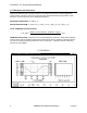
CHAPTER 11: PROGRAMMING GROUP 2 – METER CALIBRATION VOLTAGE RANGE 69.3/120V 120/208V 277/480V 5A CT High End 2.5A Low End INPUT SOURCE 75V 120V L-N 300V 5A 2.5A GROUP 2 VALUE 1440 1440 0300 2000 1000 Table 11-2: Calibration Source, Full Scale and Value Settings for Calibration 11.
CHAPTER 11: PROGRAMMING GROUP 2 – METER CALIBRATION AC VOLTS MAX MIN A B C A B C N N N B C A LM1 LM2 AC AMPS AC VOLTS MAX MIN A B C A B C N N N B C A LM1 LM2 AC AMPS A B C N A B C N MAX/MIN LIMITS VOLTS POWER PF KW KVA KVAR PF KW KVA KVAR FREQ KWH KVAH POWER AMPS POWER PHASE MAX/MIN NEXT LIMITS Step 3: a. Press AMPS to activate calibration. FREQ KWH KVAH VOLTS AMPS PHASE POWER NEXT Step 4: a. Press POWER to increase the value and PHASE/NEXT to decrease the value.
CHAPTER 11: PROGRAMMING GROUP 2 – METER CALIBRATION AC VOLTS MAX MIN A B C A B C N N N B C A LM1 LM2 AC AMPS A B C N POWER KVAH MAX/MIN LIMITS FREQ KWH VOLTS AMPS POWER PF KW KVA KVAR PHASE NEXT Step 3: ! New value moves to middle display. ! Lower display indicates the calibrated reading after 10-15 seconds. ! To enter the half scale value in lower display, a. Press VOLTS to select digits. b. Press AMPS to store and proceed to B or C within the group. c.
CHAPTER 12: GROUPS 4, 5, AND 6 – SET LIMITS AND RELAYS CHAPTER 12 GROUPS 4, 5 AND 6—SET LIMITS AND RELAYS The EPM 5300P -NL offers a comprehensive limit and set point functionality. The user can program above or below limits for every reading, including %THD. When a voltage or current measurement exceeds a particular value, the set limit is triggered and alerts the user. Each limit can trigger two internal Form C dry contact relays for alarm or secondary protection.
CHAPTER 12: GROUPS 4, 5, AND 6 – SET LIMITS AND RELAYS 12.3: Group 4, Functions 0–3—LM1/LM2 Set Limits D E S IG N A T E S G R O U P NUM BER. S IN C E T H IS IS G R O U P 4 , F U N C T IO N 0 , AC VO LTS M AX USE VO LTS TO M IN TO G G LE BETW EEN LM 1 LM 1 AN D LM 2. T H E L M 1 /L M 2 S E T L IM IT S F O R V O L T S A B C A B C N N N B C A A N , B N & C N A N N U N C IA T O R S G L O W . LM 2 AC AM PS A B C N POW ER T H E L IM IT V A L U E .
CHAPTER 12: GROUPS 4, 5, AND 6 – SET LIMITS AND RELAYS LM1 LED LM2 LED ABOVE/BELOW RELAY 1 RELAY 2 VALUE ON OFF OFF ON Digit Up Digit Down Digit Up Digit Down Digit Down Digit Up 0135 0090 Table 12.3: Group 4: Example for Function 0 EXAMPLE: If voltages exceed 135 V, LM1 is triggered and Relay 1 is enabled. If the voltages fall below 90 V, LM2 is triggered and Relay 2 is enabled. 12.4: Group 5, Functions 0–7—LM1/LM2 Set Limits AC VOLTS M AX USE VO LTS TO TO G G LE BETW EEN LM 1 AND LM 2.
CHAPTER 12: GROUPS 4, 5, AND 6 – SET LIMITS AND RELAYS THERE ARE 3 SWITCHES TO SET WITH LIMITS: 1) Switch 1: 2) Switch 2: 3) Switch 3: Sets the limit to trip either above or below the Limit Value. Sets whether Relay 1 will trip when the condition occurs. Sets whether Relay 2 will trip when the condition occurs. After the switches are set, the limit value should be programmed (see table in section 12.4).
CHAPTER 12: GROUPS 4, 5, AND 6 – SET LIMITS AND RELAYS Programming Group 6, LM1/LM2 Set Limits AC VOLTS M AX USE VO LTS TO TOG G LE BETW EEN LM 1 AN D LM 2. A B C A B C N N N B C A M IN LM 1 LM 2 AC AMPS THD A B C N POW ER T H E L IM IT V A L U E . F R O M L E F T T O R IG H T : S E T L IM IT A B O V E /B E L O W , T R IP R E L A Y 1 A N D T R IP R E L A Y 2 .
CHAPTER 12: GROUPS 4, 5, AND 6 – SET LIMITS AND RELAYS 12.5: Group 6, Functions 0–5—LM1/LM2 Set Limits and Relay Triggers for Over/Under %THD Conditions LM1 LED LM2 LED ON OFF OFF ON SWITCH 1 ABOVE/BELOW Digit Up Digit Down SWITCH 2 RELAY 1 Digit Up Digit Down SWITCH 3 RELAY 2 Digit Down Digit Up LEVEL 012.0 009.0 Table 12.9: Group 6—Example for Function 0 So, if THD exceeds 12%, LM1 is triggered and Relay 1 is enabled. If THD falls below 9%, LM2 is triggered and Relay 2 is enabled. 12.
CHAPTER 12: GROUPS 4, 5, AND 6 – SET LIMITS AND RELAYS AC VOLTS MAX MIN A B C A B C N N N B C A LM1 LM2 AC AMPS A B C N POWER KVAH MAX/MIN LIMITS FREQ KWH VOLTS PF KW KVA KVAR POWER AMPS PHASE NEXT Step 3: a. Press AMPS once. ! Lower display is replaced with three dashes.
CHAPTER 12: GROUPS 4, 5, AND 6 – SET LIMITS AND RELAYS AC VOLTS MAX MIN N N N B C A LM1 LM2 AC VOLTS MAX MIN A B C A B C A B C A B C N N N B C A LM1 LM2 AC AMPS AC AMPS A B C N KVAH MAX/MIN LIMITS FREQ KWH VOLTS AMPS POWER A B C N POWER POWER PF KW KVA KVAR PF KW KVA KVAR KVAH PHASE MAX/MIN NEXT LIMITS Step 6: a. Press VOLTS to scroll through digits. FREQ KWH VOLTS AMPS POWER PHASE NEXT Step 7: a. Press VOLTS to program the other limits and repeat this procedure. b.
CHAPTER 13: PHASE REVERSAL AND PHASE IMBALANCE SET RELAYS CHAPTER 13 PHASE REVERSAL AND PHASE IMBALANCE SET LIMITS/RELAYS 13.1: Phase Reversal and Phase Imbalance The set limit alerts the user of an unbalanced or a reversed phase in a Three-phase System. The EPM 5300P has two options for this purpose. The standard set-up is clockwise ABC rotation. Counterclockwise CBA rotation can be selected in GROUP 03.1, Switch C UP. PHASE REVERSAL: Activates when a reversed phase enters the EPM 5300P’s metering system.
CHAPTER 14: EXITING PROGRAMMING MODE 13.3: Group 7, Function 0—Voltage Phase Reversal Detection GROUP AND FUNCTION NUMBER 70. 71. 7E. FUNCTION Voltage Phase Reversal Detection Voltage Phase Imbalance Exit Programming GROUP 7 Table 13.
CHAPTER 13: PHASE REVERSAL AND PHASE IMBALANCE SET RELAYS AC VOLTS MAX MIN A B C A B C N N N B C A LM1 LM2 AC AMPS A B C N POWER LIMITS FREQ KWH KVAH MAX/MIN VOLTS PF KW KVA KVAR AMPS POWER PHASE NEXT ! Middle and Lower display indicate FUNCTION 0 settings. See Chapter 14 to exit. 13.4: Group 7, Function 1—Percentage Voltage Phase Imbalance To change the percentage voltage phase imbalance: NOTE: Press MAX/MIN/LIMITS at any time to cancel before storing the last digit or switch.
CHAPTER 14: EXITING PROGRAMMING MODE AC VOLTS MAX MIN N N N B C A LM2 AC VOLTS MAX MIN A B C A B C LM1 A B C A B C N N N B C A LM1 LM2 AC AMPS AC AMPS A B C N A B C N POWER KVAH MAX/MIN LIMITS FREQ KWH VOLTS AMPS POWER PF KW KVA KVAR POWER KVAH PHASE MAX/MIN NEXT LIMITS Step 3: a. Press AMPS to begin Data Entry Sequence. ! Lower display is replaced with two dashes. b. Press VOLTS to toggle the first segment UP (enable Relay 1) or DOWN (disable Relay 1). c. Press AMPS to store.
CHAPTER 14: EXITING PROGRAMMING MODE CHAPTER 14 EXITING PROGRAMMING MODE NOTE: Steps to exit Programming Mode vary depending on the programming stage. Exiting the Programming Mode is always necessary to store any new changes and to calculate a new checksum. Failure to exit results in a checksum error: the display blanks and the max LED flashes. IF YOU ARE LOCATED IN A FUNCTION Level—begin at Step 1. IF YOU ARE LOCATED IN A GROUP Level—begin at Step 2.
CHAPTER 14: EXITING PROGRAMMING MODE 84 EPM 5000 series Advanced Power Meters GE Multilin
CHAPTER 15: PROGRAMMING QUICK REFERENCE CHAPTER 15 PROGRAMMING QUICK REFERENCE 15.1: Entering the Programming Mode 1. Hold PHASE/NEXT key and press AMPS key. 2. Display blanks and shows either a ‘0’, ‘1’, or ‘3’. 3. If ‘3’ is not displayed then press AMPS key until ‘3’ is displayed. 4. Release AMPS key and press PHASE/NEXT key, while ‘3’ is still displayed. 5. Display shows ‘333’ momentarily. 6. Upper display starts counting. Press PHASE/NEXT key when ‘5’ is displayed to register the ‘5’. 7.
CHAPTER 15: PROGRAMMING QUICK REFERENCE 15.4: Group 0—Global Meter Setup 00. Interval. 01. Meter Address for Communication. 02. Baud Rate for Communication. 03. System Configuration Switch Packs. 030. Reserved Switches. 031. A. Blank Non Significant Leading Zeros B. Reset Protection C. Phase Reversal Rotation Selection D. Open Delta Configuration 032. A. Instantaneous/Average Limit B. Power Factor Polarity C. Modbus Options D. Protocol Selection 033. A. Computer Control Relay 1 B.
CHAPTER 15: PROGRAMMING QUICK REFERENCE 06. KYZ Programming 06P. Pulse Factor Programming 060. KYZ Port 0 Function Mapping 061. KYZ Port 1 Function Mapping 062. KYZ Port 2 Function Mapping 07. Number of Phases 15.5: Group 1: Full Scale Setup 10. Volts Full Scale 11. Currents Full Scale 12. Power Full Scale 15.6: Group 2: Calibration 20. Volt AN, BN, CN 21. Amp A, B, C (High End) 22. Amp A, B, C (Low End) 15.7: Group 3: Calibration Ratios 30. Volt AN 31. Volt BN 32. Volt CN 33. Amp A (High-End Ratios) 34.
CHAPTER 15: PROGRAMMING QUICK REFERENCE 15.9: Group 5: Power Function Limits 50. +Watt Limits 51. +VAR Limits 52. VA Limits 53. +PF Limits 54. Frequency Limits 55. –VAR Limits 56. –PF Limits 57. –Watt Limits 15.10: Group 6: THD Limits 60. Volt AN THD Limits 61. Volt BN THD Limits 62. Volt CN THD Limits 63. Amp A THD Limits 64. Amp B THD Limits 65. Amp C THD Limits 15.11: Group 7: Imbalance/Reversal Limits 70. Detect Reversal 71. Imbalance percent Limit 15.12: Group 8: DC output Calibration 8P.
CHAPTER 15: PROGRAMMING QUICK REFERENCE 8P2. Power Uni/Bi Directional Selection A. Port 4 B. Port 5 C. Port 6 D. Port 7 8P3. Power Uni/Bi Directional Selection A. Port 8 B. Port 9 C. Reserved D. Reserved 80. DC output Port 0 80F. Parameter Mapping KEY DESIGNATIONS 80L. Low-End Calibration 80H. High-End Calibration 81. DC output Port 1 MAX/MIN/LIMITS Scroll Groups Scroll Functions 81F. Parameter Mapping 81L. Low-End Calibration 81H.
CHAPTER 15: PROGRAMMING QUICK REFERENCE 90 EPM 5000 series Advanced Power Meters GE Multilin
CHAPTER 16: ETHERNET OPTION CHAPTER 16 ETHERNET OPTION The EPM5350P, Meter with the Ethernet Option, has all the components of the standard Meter PLUS the capability of connecting to multiple devices over Ethernet. The Meter face is the same as the EPM5300P (except for the model number). 16.1: Ethernet Module The Ethernet connection is made with a small module added to the back of the meter. This small but powerful module has simply an RJ-45 Port and four Status LEDs. ETHERNET 10 BASE T RJ-45 MOD.
CHAPTER 16: ETHERNET OPTION See the Table below for a description of the Status LED functions. LED Description LED Functions 1 Serial Port (Channel) 1 Status Lights solid green to indicate Channel 1 is IDLE. Blinks green to indicate Channel 1 is connected to the network and ACTIVE. 2 Serial Port (Channel) 2 Status Lights solid yellow to indicate Channel 2 is IDLE. Blinks yellow to indicate Channel 2 is connected to the network and ACTIVE.
CHAPTER 16: ETHERNET OPTION 16.3: Default IP Address The Ethernet Interface ships with a default IP address set to 0.0.0.0, whish automatically enables DHCP within the Ethernet Interface. Provided a DHCP server exists on the network, it will supply the Ethernet Interface with an IP address, gateway address and subnet mask when the Ethernet Interface boots up.
CHAPTER 16: ETHERNET OPTION ARP ON WINDOWS In order for the ARP command to work on Windows, the RP table on the PC must have at least one IP address defined other than its own. If the ARP table is empty, the command will return an error message. Type ARP –A at the DOS command prompt to verify that there is at least one entry in the ARP table.
CHAPTER 16: ETHERNET OPTION 16.7: Configuration Parameters After entering Setup Mode (confirm by pressing Enter), you an configure the parameters by entering one of the numbers on the Change Setup Menu, or you can confirm default values by pressing Enter. Be sure to store new configurations when you are finished. The Ethernet Interface will then perform a power reset. Serial Number 5415404 MAC Address 00:20:4A:54:3C:2C Software Version V01.
g GE Multilin 215 Anderson Avenue Markham, Ontario Canada L6E 1B3 Tel: (905) 294-6222 Fax: (905) 201-2098 http://www.GEindustrial.