
Industrial Systems CS300 Half Controlled Power Supply for Inverter DC-Link User`s Guide
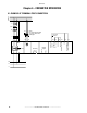
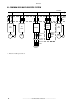


Table Of Contents
- Table of contents
- Safety Symbol Legend / Légende des Signes de Sécurité
- Chapter 1 - Safety Precautions
- Chapter 2 - Component Identification and Specification
- 2.1 General Description
- 2.2 Power Supply
- 2.3 Description of Power Terminals
- 2.4 Description of Control Terminals
- 2.5 Protections
- 2.5.1 Internal Protection Components
- 2.5.2 Internal Fuses
- 2.5.3 External AC Mains Fuses
- 2.5.4 AC Mains Choke
- 2.6 Converter Size Selection
- 2.6.1 Output Rated Currents for the Two Functioning Classes
- 2.6.2 Drive DC Current (DC Link Circuit)
- Chapter 3 - Selection of the CS300 converter
- Chapter 4 - Control Description
- Chapter 5 - Converter Dimensions
- Chapter 6 - Converter Operation
- Chapter 7 - Replacement Parts
- Chapter 8 - Warranty Parts and Service
GEH-6639
——————— INSTRUCTION MANUAL ————————
22
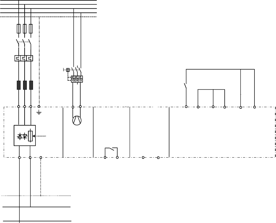
Chapter 6 - CONVERTER OPERATION
6.1 EXAMPLE OF TERMINAL STRIP CONNECTION
C
K1M
L1
L1
L2
L3
N
PE
5
1
3
24
6
5
F1
F2
1
2
3
4
6
70
72
OK Relay
UVW
PE U3 V3
CD
D
Q2
PE
PE
35
37
34
33
32 36
52
23
PRECHARGE
COMMAND
From 1050
size
Digital
output
Note !
Fan with external supply
only from 1050A size
and higher
MLP
ML
Precharge
enable
Common
MLP&ML
GND 24
Common
Precharge enable
24V
Power supply of
the ML and MLP