Autotrol®Performa™ ProSoft With 960 Series Control 5-Cycle Conditioner 5-Cycle FA Filter Water Conditioning Control System Installation, Operation and Maintenance Manual
Table of Contents Installation . . . . . . . . . . . . . . . . . . . . . . . . . . . . . . . . . . . . . 3 Location Selection Water Line Connection Drain Line Connection Regenerant Line Overflow Line Connection Placing Conditioner into Operation . . . . . . . . . . . . . . 5 Electrical Connection 960 ProSoft Control . . . . . . . . . . . . . . . . . . . . . . . . . . . . . 6 Programming Level I Features Level II Features Manual Regeneration Automatic Regeneration Performa 960 FA Control . . . . . . . . .
Installation All plumbing and electrical connections must conform to local codes. Not in Bypass Out In In Bypass Out In Inspect unit carefully for carrier shortage or shipping damage. BY PA S S Water Conditioner 3. Since salt must be added periodically to the regenerant tank, the location should be easily accessible. PA S S PA S S PA S S 2. If it is likely that supplementary water treatment equipment will be required, make certain adequate additional space is available. BY BY 1.
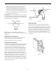
. Where the drain line is elevated but empties into a drain below the level of the control valve, form a 7-inch (18-cm) loop at the far end of the line so that the bottom of the loop is level with the drain line connection. This will provide an adequate siphon trap. Overflow Fitting Installed Regenerant Tank 5. Where the drain empties into an overhead sewer line, a sink-type trap must be used. IMPORTANT: Never insert drain line into a drain, sewer line or trap.
Placing Conditioner into Operation 5. Place the conditioner into operation. After all previous steps have been completed, the unit is ready to be placed into operation. Follow these steps carefully. A. With the water supply valve completely open, carefully advance the cycle indicator COUNTERCLOCKWISE to the center of the REFILL position. Hold at this position until water starts to flow through the regenerant line into the regenerant tank. Do not run for more than one or two minutes. B.
960 ProSoft Control Conditioner Systems Cycle Indicator Regen Button Press the SET button and the far right number on the display starts flashing. If you want to change this number, press the up arrow (↑) button to increase the number or the down arrow (↓) button to decrease the number. To skip the number without changing, press the left arrow (←) button. When you reach the far left digit, pressing the left arrow (←) button will return you to the far right digit.
amount. The default value is 1.0 kilograin (0.1 kilogram). If this is not acceptable, press the SET button and enter a new value. Any value between 0.1 and 140 kilograins (.01 and 14.00 kilograms) is allowed. Time of Regeneration The next value displayed is the Time of Regeneration. It has a default value of 2:00 a.m. If this is not acceptable, press the SET button and change the number. Press the SET button to enter the value. If 2:00 a.m. is acceptable, press the down arrow (↓) button.
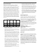
Table 2 - Suggested Salt Dial Settings (Pounds of Salt) For Various Size Softeners - P1 through P5 Capacity Setting (Kilograins) 12 16 20 24 30 32 35 40 48 60 0.5 Ft3 0.75 Ft3 1.0 Ft3 1.25 Ft3 1.5 Ft3 1.75 Ft3 2.0 Ft3 2.5 Ft3 4.6 9.0 — — — — — — — — — 5.6 8.6 14.0 — — — — — — — — 6.0 8.6 15.0 18.6 — — — — — — — 7.0 11.0 12.6 16.0 23.0 — — — — — — 9.0 10.0 12.0 17.0 28.0 — — — — — — 9.0 10.0 14.0 21.0 — — — — — — — 9.0 12.0 17.0 30.0 — — — — — — — — 14.0 21.
Table 3 - Level II Programming Parameters Parameter Name Description Range of Values Minimum Increments Default Units of Measure P6 Refill controller 1 to 99 1 33 1 to 99 1 25 NA NA NA NA P8 Regenerant draw value Not used P9 Backwash time 3 to 30 1 14 Minutes P10 Slow rinse time 8 to 125 1 40 Minutes P11 Fast rinse time 2 to 19 1 4 Minutes P12 Units of Measure 0 to 1 1 0 P13 Clock mode 0 to 1 1 0 P14 Calendar override 0 to 30 1 0 P15 Reserve type 0 to 3
• Parameter P18 allows the installer to lock the Salt Regenerant Draw Value Amount and Capacity values so they cannot be changed. When Parameter 18 is set to 1, those two settings can only be viewed when the control is in the Level II mode. The settings will be skipped when the control is in the Level I mode. When Parameter 18 is set to zero, the Salt Amount and Capacity can be viewed and changed in either Level I or Level II. Parameter P7 is used by the control to calculate the regenerant draw time.
Automatic Regeneration Since a new installation has no history of water usage, the control multiplies the percent of capacity value set in Parameter P16 by the total system capacity to determine starting average for each day of the week. The factory set default value for P16 is 30 which means that 30% of the total system capacity is used for the starting average for each day.
Performa 960 FA Control 5-Cycle Filter System Performa 960 FA Level I Parameters (Table 5) Level I Parameters are identified as those that have an LED indicator on the front panel. The green indicator illuminates next to the name of the active control setting. The end user has access to all of these parameters.
Time of Day Regenerant Dosage Press the SET button. The display will show the Time of Day with the minutes digit blinking. If you want to change this number, press the UP ARROW (↑) button to increase the number or the DOWN ARROW (↓) button to decrease the number. To skip the number without changing, press the LEFT ARROW (←) button. The first number stops flashing and the next number starts flashing. You can only change the flashing number.
Table 5 -Performa 960 FA Level I Programming Parameters Parameter Range of Values Minimum Increments Default Units of Measure Notes 1 None Hour: minute Range depends on value selected for P13. Enter the current time. Name Description P1 Time of day AM or PM 1:00 to 12:59 00:00 to 23:59 P2 Time of day of regeneration 1:00 to 12:59 AM or PM 00:00 to 23:59 1 2:00 AM Hour: minute Range depends on value selected for P13. Skip this parameter to accept the default or enter a new time.
Table 8 - Performa 960 FA Level II Programming Parameters Parameter Range of Values Minimum Increments Default Units of Measure Notes Name Description P6 Refill controller 1 to 99 1 33 Must be set to 46 for Performa 960 FA operation P7 Regenerant draw value 1 to 99 1 25 Select Regenerant Draw value from Table 9 and enter that number. P8 Not used NA NA NA NA NA P9 Backwash time 3 to 30 1 14 Minutes Skip this parameter to accept the default or enter a value.
Performa 960 FA Level II Parameters does not match your installation, press the SET button and enter a new value. Refer to Table 9 for the correct value. The injector cap is labeled with the injector letter. The injector is color coded for easy identification. Next, determine the typical water pressure for this installation. The Regenerant Draw value is an estimate of the flow rate of regenerant through the injector. This rate varies with water pressure and injector type as shown in Table 9.
show the Regen Time Remaining as an indication that the second regeneration will be performed. When the first regeneration is complete, the second one will begin and the display will alternate between Time of Day and Regen Time Remaining. total capacity by the percentage entered for Parameter P16 and uses that value as the initial average daily usage for each day of the week until water usage establishes new averages. The default is set for 30% of the capacity. In most installations this is acceptable.
Water Usage Pattern Preventive Maintenance The other reserve option allows the control to adjust the reserve based upon the historical water usage pattern of the system. The control keeps track of the water usage for each day of the week and uses that day’s average usage multiplied by 1.2 as the reserve for that day. Every day at the Time of Regeneration, the control recalculates the day’s average water usage.
Water Meter Maintenance The metering device used with the 960 demand controls may require simple maintenance. In rare instances, the turbine wheel of the water meter can collect small particles of oxidized iron, eventually preventing the wheel from turning. Tab 1. Shut off the water supply or put the bypass valve(s) into the bypass position. 2. Relieve pressure by opening the Backwash Drain Valve (the seventh back from the control) with a screwdriver (Figure 9). 3.
Figure 14 6. Disconnect the turbine probe from the turbine assembly. 7. Lift the control off the valve, Figure 15. To replace the control, reverse the above procedure. Note that the camshaft needs to be positioned correctly before it can be inserted into the back of the control. There is a locating arrow on the camshaft. Position the arrow on the top of the shaft and slide the camshaft into the control. Push up on the end of the camshaft, furthest from the timer, snapping it into place.
Specifications Hydrostatic Test Pressure . . . . . . . . . . . . . . . . . . . . . . . . . . . . . . . . . . . . . . . . . . . . . . . . . . . . . . . . . . . . . . . . . . . . . . . . . . . . 300 psi (20.69 bar) Working Pressure . . . . . . . . . . . . . . . . . . . . . . . . . . . . . . . . . . . . . . . . . . . . . . . . . . . . . . . . . . . . . . . . . . . . . . . . . . . . 20-125 psi (1.38 - 8.62 bar) Standard Electrical Rating . . . . . . . . . . . . . . . . . . . . . . . . . . . . . . . . . . . . .
Pressure Graphs Injector #1031363 Injector #1031364 "A" in a 268 Valve "B" in a 268 Valve 1.00 0.30 0.20 Total 1.25 0.25 0.75 0.20 Rinse 0.05 0.00 0.50 Brine Draw 0.15 0.75 GPM 0.10 M3/hr Rinse GPM M3/hr 0.15 Total 1.00 0.10 0.50 0.05 0.25 0.00 0.00 Brine Draw 0.25 0.00 20 40 400 600 60 PSI 80 100 120 20 800 1000 1200 1400 1600 1800 bar 40 400 600 60 1.25 0.20 0.10 0.05 M3/hr Rinse GPM M3/hr 0.25 Total 0.75 0.10 Brine Draw 0.50 0.05 0.25 0.00 0.15 0.
Valve Disc Principle of Operation Identification of Control Valving 7 Backwash Drain Valves 5 Refill Valve 3 Inlet Valve 1 Regenerant Valve 6 Rinse Drain Valve 4 Outlet Valve 2 Bypass Valve Flow Diagrams 1 Service Position 2 Backwash Position Hard Water Hard Water Soft Water Soft Water Inlet Inlet 3 3 2 2 5 5 Outlet Valve No. 1 - Closed 2 - Closed 3 - Open 4 - Open 5 - Closed 6 - Closed 7 - Closed Brine Adjustment 1 Brine Adjustment 1 4 Outlet 6 Valve No.
4 Purge Position 3 Brining/Slow Rinse Position Hard Water Hard Water Soft Water Soft Water Brine Adjustment 1 Inlet Inlet 3 2 3 2 5 Outlet 4 5 6 Outlet 7 Drain Valve No. 1 - Open 2 - Open 3 - Closed 4 - Closed 5 - Closed 6 - Open 7 - Closed Brine Adjustment 1 4 6 7 Drain Mineral Tank Valve No.
Replacement Parts Performa Valve 15 2 12 3 12 4 14 13 9 8 5 6 1 11 7 10 25
Parts List Part Code Part Qty. Code 1 1035807 No. Valve Assembly, w/o Flow Controls 1 11 2 1035615 960 Standard Camshaft: 1 12 Drain Control Assembly: 1 3 4 No. 1035622 1001606 Description 1 Plumbing Adapter Kits: 1 3/4-inch Copper Tube Adapter Kit No. 7 (1.2 gpm; 4.5 Lpm) 1001670 1-inch Copper Tube Adapter Kit 1000210 No. 8 (1.6 gpm; 6.1 Lpm) 1041210 1-1/4-inch Copper Tube Adapter Kit 1000211 No. 9 (2.0 gpm; 7.6 Lpm) 1001608 22-mm Copper Tube Adapter Kit 1000212 No.
960 ProSoft Control 1265 Bypass Performa ProSoft B Y PA S S B Y PA S S 2 1 Part Code Performa FA No. Description Qty. 1 960 ProSoft Control 1 2 FA 1 3 1040930 1265 Bypass 1 * 1000811 Transformer 1 * 1000907 Transformer Extension Cord 1 15 feet (4.
Troubleshooting IMPORTANT: Service procedures that require the water pressure to be removed from the system are marked with a ! after the possible cause. To remove water pressure from the system, put the bypass valve or three-valve bypass into the bypass position and open the backwash drain valve (the seventh valve back from the control) with a screwdriver. Restore system water pressure when the service work is completed.
960 Control Troubleshooting Alarms The Model 960 continuously monitors itself and sounds an alarm if it detects something wrong. The alarm is a beep that is on for one second and then off for nine seconds. When the alarm sounds, the display shows the letters “Err” with a number from 1 to 4. The table below lists the Err numbers, a description of each error, the cause of the error, and the solutions. To silence the alarm, press any button on the control.
Problem 6. No water flow display when water is flowing (colon does not blink). Possible Cause A. B. C. Solution Bypass valve in bypass position. Meter probe disconnected or not fully connected to meter housing. Restricted meter turbine rotation due to foreign material in meter ! A. B. Shift bypass valve into service position. Fully insert probe into meter housing. C. D. E. Remove meter housing, free up turbine and flush with clean water. Turbine should spin freely.
Disinfection of Water Conditioners 2. Regenerant tank conditioners The materials of construction of the modern water conditioner will not support bacterial growth, nor will these materials contaminate a water supply. However, the normal conditions existing during shipping, storage and installation indicate the advisability of disinfecting a conditioner after installation, before the conditioner is used to treat potable water.
© Copyright 2005 General Electric Company Printed in USA P/N 1227756 Rev.