
User Manual


18 49-2000707 Rev. 0
INSTALLATION INSTRUCTIONS
Installation Instructions
1
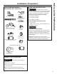
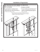
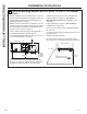
INSTALL HOOD SUPPORT
IMPORTANT: Framing must be capable of
supporting 100 lbs for 30" and 36" models and 150
lbs for 48" models.
• Locate a minimum of 2 vertical studs for the
installation bar by tapping drywall with a hammer
or use a stud finder.
• Level the installation bar and center left to right
above the marked line. Hold bar against the wall.
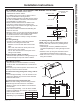
• Drill 1/8” pilot holes at the 2 vertical stud locations
through holes in the installation bracket. Secure
the installation bar with supplied screws (A) as
shown above.
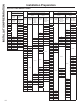
Drill Bottom Mounting Hole Locations:
• Hang hood on installation bar or use the table
below to mark the screw hole locations. NOTE: If
installing to the soffit or cabinet, push hood flush
to the soffit or cabinet before marking screw hole
locations.
• Remove the hood and drill 5/16” clearance holes at
marked locations “A” and “B”.
2
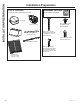
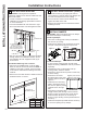
INSTALL DAMPER
IMPORTANT: Remove shipping tape from damper
and check that damper moves freely.
Install Top Damper:
• The motor mounting plate comes pre-installed in
the hood for top venting.
• Install the top damper to the hood body as shown
in Figure A using screws (B) from top of hood.
Install Back Damper:
• In case of back venting through the wall, back
damper accessory UXBDA812 must be purchased
separately.
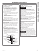
• Uninstall the motor mounting plate from top
venting position. Save the screws.
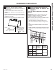
• Remove the square knockout panel on hood body
for back venting.
• Remove the two screw
knockout holes on the motor
mounting plate as shown in
Figure C.
• Install the motor mounting
plate to back panel so that
the arrow on plate is pointing
upwards and on the right
side.
• Push plate in until metal clips
engage. Fasten plate through screw knockouts
shown in Figure C using the two screws saved.
• Install the back damper to the hood body as
shown in Figure B using screws provided with the
accessory.
• Install the metal plate provided with the accessory
to cover the opening for top damper.
Installation Bar
Centerline of
Installation Space
16-3/4”
24” minimum over electric
range or cooktop, or
30” minimum over gas
range or cooktop, and 36”
recommended maximum.
Figure A
Figure B
1
INSTALL HOOD SUPPORT (Cont.)
• Install wall anchors (C) by tapping the anchors
with a hammer to seat the teeth of the flanges into
the wall. This keeps anchor from rotating.
• Drive the anchor screws until the barrels crimp
against the inside of the wall.
• Remove the screws from the wall anchors before
installing the hood.
B
A
Bottom of Hood
Centerline of
Installation Space
“A” “B”
30” Model 8-3/4”
5”36” Model 13-3/4”
48” Model 17-3/4”
TOP
Figure C (Panel will look
different for single motor)
Screw Knockouts