Installation Instructions If you have questions, call 800.GE.CARES or visit our website at: www.monogram.
Safety Information CAUTION: BEFORE YOU BEGIN Due to the weight and size of this refrigerator, and to reduce the risk of personal injury or damage to the product – TWO PEOPLE ARE REQUIRED FOR PROPER INSTALLATION. Read these instructions completely and carefully. • IMPORTANT – Save these instructions for local inspector’s use. • IMPORTANT PRUDENCE : – Observe all governing codes and ordinances. • Note to Installer – Be sure to leave these instructions with the Consumer.
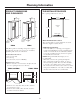
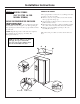
Planning Information THE INSTALLATION SPACE PRODUCT DIMENSIONS AND CLEARANCES 32" Depth The opening width must be 36-1/4". 36-1/2" 28" Depth 72" Wall View 72-1/4" 73" min. Electrical Area Water Supply 36" 36" 30-1/2" Including Handles 34" Including Handles Water And Electrical Locations The opening must be prepared with the electrical and water supply located as shown. ZFSB25 ZFSB26 Additional Specifications • A 115 volt 60Hz., 15 or 20 amp power supply is required.
Installation Instructions TOOLS REQUIRED FLOORING • Tinsnips to cut banding • Stepladder • Bucket • Level • Appliance hand truck • Tubing cutter • #2 Phillips screwdriver • Drill and appropriate bits • 3/8", 5/16" and 7/16" hex socket • 1/8" Allen wrench • Safety glasses For proper installation, this refrigerator must be placed on a level surface of hard material that is at the same height as the rest of the flooring. This surface should be strong enough to support a fully loaded refrigerator.
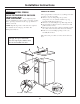
Installation Instructions REMOVE THE DOORS STEP 1 MODEL ZFSB25 The top cap must be removed to access hinges. It is best to remove one door at a time. A. Remove 2 screws on top and 2 screws at the back of the top cap. Lift off top cap. B. Open both doors. Remove the 2 toekick screws and pull forward to remove. C. Disconnect the water line coupler by pushing against the collar on the left side. Disconnect wire harness. D. Remove 2 screws holding top hinge to the case. Carefully lift off door.
Installation Instructions STEP 1A MODEL ZFSB26 REMOVE THE DOORS MOVE REFRIGERATOR INDOORS The top cap must be removed to access hinges. It is best to remove one door at a time. A. Remove 2 screws and springs on top of the refrigerator, one on each side. Push the top cap forward and lift up from the rear. B. Remove 2 screws holding the top filler strip, lift off. C. Open both doors. Remove the 2 toekick screws and pull forward to remove. D.
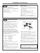
Installation Instructions STEP 1 ALL MODELS (continued) REINSTALL DOORS Refer to the illustration on page 5 or 6. • Carefully, route the water line tubing and electrical through the freezer side bottom hinge. Lower the door onto bottom hinge. • Secure top hinge. • Insert the tubing all the way into the coupler. • Reconnect the wiring harness. • Replace top filler strip (on model ZFSB26). • Replace top cap with original screws and springs (where present).
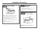
Installation Instructions Step 2A WATER LINE INSTALLATION WITH A REVERSE OSMOSIS SYSTEM STEP 3 CONNECT WATER SUPPLY Skip this step when not using RO System Tubing Clamp Check to be sure that refrigerator power cord is not plugged into the wall outlet. 1/4" Compression Nut IMPORTANT: When connecting a GE Reverse Osmosis Water System to your refrigerator, the GE RVKit must be used. For other reverse osmosis water systems, follow the manufacturer’s recommendations.
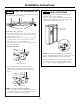
Installation Instructions STEP 6 LEVEL THE REFRIGERATOR STEP 7 LEVEL THE DOORS The refrigerator can be leveled by adjusting the rollers located near the bottom hinges. If the doors are not evenly aligned at the top, the refrigerator door can be adjusted. • Use a 7/16" hex socket or wrench to turn the door adjusting screw. Turn the screw to the right to raise the door, turn left to lower the door.
Installation Instructions STEP 9 TEMPERATURE CONTROLS STEP 8 START ICEMAKER • The temperature controls are preset at 37° for the refrigerator and 0°F for the freezer. • Allow 24 hours to stabilize before making adjustments. Power Switch STEP 10 INSTALL TOEKICK Feeler Arm • Press toekick into position and reinstall one screw on each side. • Flip the switch to I (ON) position. The icemaker will not begin to operate until it reaches its operating temperature of 15°F (–9°C)or below.
Notes 11
NOTE: While performing installations described in this book, safety glasses or goggles should be worn. For Monogram® local service in your area, call 1.800.444.1845. NOTE: Product improvement is a continuing endeavor at General Electric. Therefore, materials, appearance and specifications are subject to change without notice. Pub. No. 49-60476 Dwg. No. 197D4577P002 07-06 JR Printed in Mexico GE Consumer & Industrial GE Appliances General Electric Company Louisville, KY 40225 ge.