
Appliance Trim Kit User Manual


Table Of Contents
- Chapter 1 Overview
- Chapter 2 C400 Panel Controller Hardware
- General Information
- Genius Panel Controller (C400)
- Specifications
- Overview of Connections and Operational Elements
- VDC Power Supply (item 2, Figure 2-2)
- IF0 - RS-232, Non-isolated (item 3, Figure 2-2)
- Genius Bus Connector, Isolated (item 4, Figure 2-2)
- Mode Switch (item 6, Figure 2-2)
- Device Number Switches (item 8, Figure 2-2)
- Lithium Battery (item 7, Figure 2-2)
- Reset Button (item 9, Figure 2-2)
- Operating the C400 Controller
- Chapter 3 Quick Start
- Calling the Setup Program
- Language Selection
- Installation Menu
- Pull-Down Menus (Main Menu)
- Window Name
- Selection Windows
- Context-Sensitive Help Screens
- Screen Elements
- Connection to a GE Fanuc PLC via Genius
- Internal Connection
- Genius Internal Connection
- Picture 1
- Picture 2
- Picture 3
- Genius Device Connection
- Genius Internal Connection
- Internal Connection
- Picture for a Communications Error
- Picture Binding Overview
- Picture List Organization
- Chapter 4 Configuring Communication with the PLC
- Chapter 5 PCS Connection Editor
- Chapter 6 Demo Project
- Appendix A Cabling Information
- Appendix B Errors/Troubleshooting
- Index
2 - 6 PANELWARE MMI Application Manual for Genius Protocol - June 1995 GFK-1115
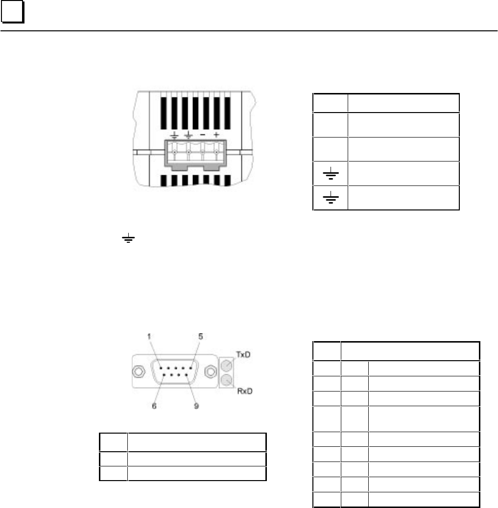
2
24 VDC Power Supply (item 2, Figure 2-2)
Pin
Description
+
+24 V
-
0 V
Ground
Ground
The pins are to be connected using as short a cable as is possible. If the Panel is mounted in a
cabinet, the connecting cable should be as short as possible.
IF0 - RS-232, Non-isolated (item 3, Figure 2-2)
9 pin D-Type (M)
LED Meaning
TxD Send data over interface
RxD Receive data over interface
Pin Description
1NC
2 RxD Receive Data (Input)
3 TxD Transmit Data (Output)
4 + 5 V Power Supply
(200 mA available to user)
5 GND Signal Ground
6NC
7 RTS Request To Send (Input)
8 CTS Clear To Send (Output)
9NC