
Appliance Trim Kit User Manual


Table Of Contents
- Chapter 1 Overview
- Chapter 2 C400 Panel Controller Hardware
- General Information
- Genius Panel Controller (C400)
- Specifications
- Overview of Connections and Operational Elements
- VDC Power Supply (item 2, Figure 2-2)
- IF0 - RS-232, Non-isolated (item 3, Figure 2-2)
- Genius Bus Connector, Isolated (item 4, Figure 2-2)
- Mode Switch (item 6, Figure 2-2)
- Device Number Switches (item 8, Figure 2-2)
- Lithium Battery (item 7, Figure 2-2)
- Reset Button (item 9, Figure 2-2)
- Operating the C400 Controller
- Chapter 3 Quick Start
- Calling the Setup Program
- Language Selection
- Installation Menu
- Pull-Down Menus (Main Menu)
- Window Name
- Selection Windows
- Context-Sensitive Help Screens
- Screen Elements
- Connection to a GE Fanuc PLC via Genius
- Internal Connection
- Genius Internal Connection
- Picture 1
- Picture 2
- Picture 3
- Genius Device Connection
- Genius Internal Connection
- Internal Connection
- Picture for a Communications Error
- Picture Binding Overview
- Picture List Organization
- Chapter 4 Configuring Communication with the PLC
- Chapter 5 PCS Connection Editor
- Chapter 6 Demo Project
- Appendix A Cabling Information
- Appendix B Errors/Troubleshooting
- Index
A - 6 PANELWARE MMI Application Manual for GE Fanuc Genius Protocol - June 1995 GFK-1115
A
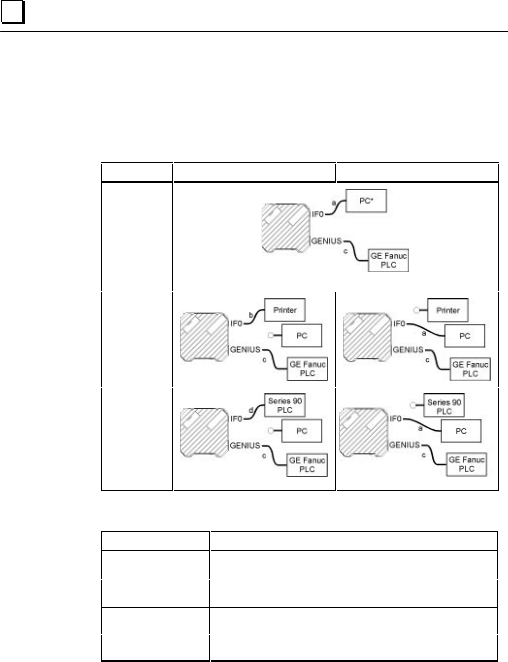
Cable Diagrams
Table A-2 provides an overview of the cabling possibilities for connecting PANELWARE Panels,
PLCs, printers and PCs (with PCS installed and running). Table A-3 lists the locations of pin-out
diagrams in the PANELWARE documentation.
Table A - 2. Cable Diagrams for Various Configurations
Configuration Run Mode Teach Mode
C400
+ Series 90 PLC
(no printer)
* The PC does not need to be connected in RUN mode.
C400
+ Series 90 PLC
+ printer on IF0
C400
+ Series 90 PLC
(serial)
+GE Fanuc PLC
(Genius)
Table A - 3. Pin-out Diagram Locations in Documentation
Cable (see Table A-1) Manual and Chapter/Appendix
a (Panel to PC)
PANELWARE Hardware Installation User's Manual (GFK-0848)
Appendix A Cabling Information (Connection to the PC)
b (Panel to printer)
PANELWARE Hardware Installation User's Manual (GFK-0848)
Chapter 7 “Printers”
c (Panel to CPU —
Genius)
Pages A-2 through A-6,
PANELWARE MMI Application Manual for
GE Fanuc Genius Protocol
— GFK-1115 (this manual)
d (Panel to CPU — SNP)
PANELWARE™ MMI Application Manual for GE Fanuc Series 90 Protocol
(SNP) —
GFK-0850