
Appliance Trim Kit User Manual


Table Of Contents
- Chapter 1 Overview
- Chapter 2 C400 Panel Controller Hardware
- General Information
- Genius Panel Controller (C400)
- Specifications
- Overview of Connections and Operational Elements
- VDC Power Supply (item 2, Figure 2-2)
- IF0 - RS-232, Non-isolated (item 3, Figure 2-2)
- Genius Bus Connector, Isolated (item 4, Figure 2-2)
- Mode Switch (item 6, Figure 2-2)
- Device Number Switches (item 8, Figure 2-2)
- Lithium Battery (item 7, Figure 2-2)
- Reset Button (item 9, Figure 2-2)
- Operating the C400 Controller
- Chapter 3 Quick Start
- Calling the Setup Program
- Language Selection
- Installation Menu
- Pull-Down Menus (Main Menu)
- Window Name
- Selection Windows
- Context-Sensitive Help Screens
- Screen Elements
- Connection to a GE Fanuc PLC via Genius
- Internal Connection
- Genius Internal Connection
- Picture 1
- Picture 2
- Picture 3
- Genius Device Connection
- Genius Internal Connection
- Internal Connection
- Picture for a Communications Error
- Picture Binding Overview
- Picture List Organization
- Chapter 4 Configuring Communication with the PLC
- Chapter 5 PCS Connection Editor
- Chapter 6 Demo Project
- Appendix A Cabling Information
- Appendix B Errors/Troubleshooting
- Index
6 - 14 PANELWARE MMI Application Manual for GE Fanuc Genius Protocol - June 1995 GFK-1115
6
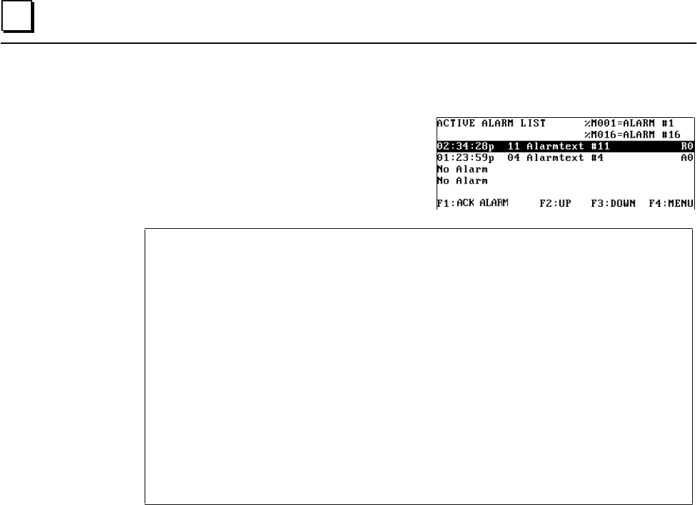
Alarm List
Pressing the F4 key while in the main menu
causes the ACTIVE ALARM LIST to appear on
the Panel display:
Key LEDs:
Alarms are displayed according to an alarm bit field that is found in memory location %M001
through %M016 in the PLC. For example, if %M008 is changed from 0 to 1 in the PLC, alarm 8
is entered in the alarm list. (More information about the alarm bit field structure in the PLC can be found in
chapter 4.) Also, see the PANELWARE™ Configuration Software Reference Manual (GFK-0849)
for a more detailed description of alarms.
An entry in the list contains the following information:
Alarm time When the alarm occurred
Alarm number Number of the alarm (corresponds to the bit number in the alarm bit field)
Alarm text Short description of the alarm
Information Information about the type of alarm
Priority Priority of the alarm
The following functions are assigned to keys F1
– F3:
F1 Acknowledgment for the selected alarm.
F2/F3 Scroll through the alarms in the alarm list (F2=Up; F3=Down). Scrolling
through the list selects an alarm (inverse display), which can be acknowledged
by pressing the F1 key.
Pressing the F4 key returns you to the main menu.