
User's Manual
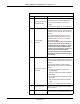
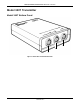
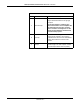
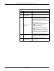
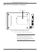
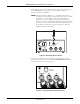
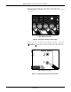
Table Of Contents

Revision B Model 340 Telemetry System 3-5
2003720-001
Controls, Indicators, and Connectors: Model 340R Receiver
Table 3-2. Receiver Rear Panel
Name Description
A
AC Line Connector and
Fuseholder Module
This module houses the AC-line input connector
and the main fuses for the Model 340R Receiver:
n
100–120 VAC: requires two, 1 A slow-blow
fuses.
n
220–240 VAC: requires two, 1 A time-lag fuses.
B
Auxiliary Output
Connector
This connector is used with 120 and 170 Series
Monitors only. Do not use this connection method
for Models 115, 116, 118, 145, 150, 151, and 155
Monitors.
This connector outputs the US, ECG, UA, and
Mark signals, acquired by telemetry, to a 120 or
170 Series Monitor. See page 4-5 for complete
interconnection details.
As soon as any telemetry mode is detected, the
front panel of the 120 or 170 Series Monitor is
disabled and all front panel inputs are ignored.
In other words, telemetry and monitor modes
cannot be “mixed and matched’; you must use
telemetry only or direct monitoring only.
For proper operation with a 170 Series Monitor,
disconnect all transducers from the front panel
of the monitor.
C
US, ECG, UA, and Mark
Connectors
These connectors are used with Models 115, 116,
118, 145, 150, 151, and 155 Monitors only. Do not
use this connection method for 120 and 170 Series
Monitors.
Each connector outputs the respective signal,
acquired by telemetry, to the fetal or maternal/fetal
monitor:
n
US: light grey connector which outputs the
ultrasound signal.
n
ECG: grey connector which outputs the FECG or
MECG signal.
n
UA: white connector which outputs the TOCO or
IUPC signal.
n
Mark: connector which outputs the Event Mark
signal.
See page 4-2 for complete interconnection details.
D Antenna Connector
Twist-on connector for attaching the Model 340R
Receiver antenna.
E Equipotential Lug
Binding post terminal directly connected to the
chassis for use as an equipotentiality connection.