
User's Manual

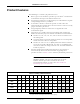

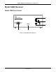
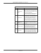
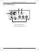
Table Of Contents

Revision B Model 340 Telemetry System 3-3
2003720-001
Controls, Indicators, and Connectors: Model 340R Receiver
Table 3-1. Receiver Front Panel
Name Description
A
UA Mode Selector
Switch
This switch communicates the active uterine
activity mode to the fetal or maternal/fetal monitor:
n
When monitoring with a tocotransducer, set the
switch to the TOCO position.
n
When monitoring with an intrauterine pressure
catheter, set the switch to the IUP position.
B Channel Number
The channel number is the customer-designated
receiving frequency of the Model 340R Receiver.
For each telemetry system, the channel number of
the receiver must be identical to the channel
number of the transmitter. Also, if you have more
than one telemetry system, or other RF devices,
each system must have a unique channel number.
C
Power Switch and
Indicator
The Power switch turns the receiver on (I) and off
(O). When set to on, the green Power indicator
illuminates.
D Low Battery Indicator
The red Low Battery indicator flashes when you
have approximately 10 minutes of Model 340T
Transmitter battery power remaining. The Low
Battery indicator stops flashing and lights
continuously as soon as the battery is depleted.
E Signal Indicator
The green Signal indicator lights continuously
when the receiver is accepting radio frequency
signals from the transmitter. The Signal indicator
flashes if the signal strength is weak or marginal.