
User's Manual


7
1.0/November 1998 1891 1210
Section 2
Operation
2.1 USER CONNECTIONS
Connection to the ST500 transmitter is made via three headers, PL1, PL2 and PL3,
which plug directly into the user's own equipment. The location of these connectors is
shown in the General Arrangement drawing given at the back of this manual.
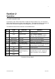
The details of these three connectors are detailed below:
PIN NAME FUNCTION REMARKS
1 0V 0 volts common ground
2 bT bXbE transmit enable o/c = transmitter disabled
LOW <+0.8V = transmitter enabled
1KÙ nom. internal pull-up to +Vin
3 DIGITAL I/P data input 0/+3V to 0/+12V, DC-coupled
4 ANALOGUE I/P data input 300mV to 5V p-p, AC-coupled
5 +5V O/P +5V supply output 50mA max. current drain
6 RS232 I/P serial programming
input
If not used leave un-connected or ground.
(refer to section 3.5 for details)
7 0V 0 volts common ground
8 RB1
parallel frequency
select
internal pull-up to +5V, active low
(refer to section 3.5.4 for details)
9 RB2
10 RB3
Connector PL1 pin detail