
Operating Instruction

Simplified Operating Instruction, 340M OB Telemetry, 608-614MHz
GE Medical Systems Information Technologies 4/9/01
Page 4 of 8
Left position
LEVEL mmHg:
Set to 100
MODE:
Set to TOCO
Bottom Center section
MANUAL ADJUSTMENT:
Full clockwise
PATTERN MEMORY:
ON
Bottom Right
POWER indicator:
Glows green when AC power connected and rear panel switch depressed
Rear Panel:
Power inlet:
Connect IEC style power cord to 120 VAC
Power button:
Push on/ Push off style button. 325 must be powered on for testing.
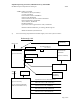
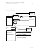
Cable Harness, Front Panel:
From Top Center (3) gray cables are connected from ‘CONNECT TO FETAL MONITOR’
connector.
-Round white to UA input jack of 341 Transmitter
-Round Gray/Blue to ULTRASOUND input jack of 341 Transmitter
-Round dark gray to ECG input jack of 341 Transmitter
Procedure:
1) Identify packed items.
- 341M Telemetry Receiver
- Line cord
- System Interconnect cable #1563AAO
- Mark interconnect cable #1397AAO
- US interconnect cable #1399BAO
- ECG interconnect cable #1375AAO
- UA interconnect cable #1400AAO
- Quarter wave stainless whip antenna (receiver)