
User Manual
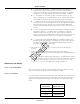
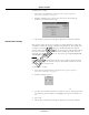
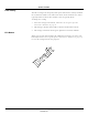
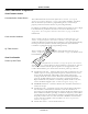
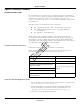
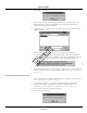
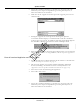
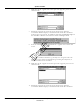
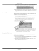
Table Of Contents
- Contents
- 1 Introduction
- 2 Apex Transmitter
- 3 ApexPro CH Transmitter
- Program the Transmitter’s Basic Functions
- View Transmitter Diagnostics
- Update Transmitter Firmware
- ApexPro CH Appendices
- 4 ApexPro Transmitter

Revision A - Draft 7 APEX, ApexPro, and ApexPro CH Transmitter Programming Instructions 61
2001989-135
ApexPro Transmitter
c – View the Label. This is a combination of the TTX number and an
abbreviation of the transmitter model. The label automatically
changes as you change the TTX Number. For example, an ApexPro
transmitter set at TTX number 7700 would be labeled “7700AP”.
d – View Other Transmitters at This Frequency. If there are any
other transmitters set to this frequency, there could be interference
with signals from this transmitter. Avoid this whenever possible.
e – Check the Clear Failures With This New Setting box. This resets
any failed status that was indicated in the Power-up Self-Test Status
section of the Program ApexPro Transmitter window. When this
option is checked, failures will be cleared when you select the OK
button.
f – View Incompatible Transmitters. Incompatible transmitters have
frequencies within +/
– 12.5 KHz. These transmitters cannot be
admitted on the same system. If a list of any other transmitters
appears in this box, the TTX number selected cannot be used and the
OK button is disabled. You must select a different TTX Number.
g – Channel and Zone (JAPAN ONLY) are coordinated with TTX
Number in that they change as you change the TTX Number. Refer to
the Apex
and ApexPro
Transmitter Programming Instructions
(Japan) document for specific usage.
4. Select OK to save your changes or Cancel to revert to the original
settings.
5. Update the “TTX Frequency Chart” in the ApexPro Telemetry
Transmitter Service Manual to identify changes to the TTX numbers and
the frequencies.
6. Select the appropriate TTX label for ApexPro V1, V2 from the label sheet
and apply it to the transmitter inside the label depression located on the
back of the transmitter. (See “Appendix 3: ApexPro TTX Labels and
Frequencies” on page 80 for applicable label part numbers.)
Reference Lead Setting
For 5- or 6-Lead Cables
The reference lead setting has no effect when 5- or 6-lead cables are used.
For 5- or 6-lead cables, the reference lead defaults to RL.
For 3-Lead Cables
For 3-lead cables, one of the lead wires (LL, LA, or RA) is used to connect the
reference voltage to the patient. Selection of the reference lead determines
which ECG waveform will be displayed at the CIC, according to the table
below.
Select this
reference lead...
to view this
waveform at the CIC
Lead I LL (left leg)
Lead II LA (left arm)
Lead III RA (right arm)
Draft