
User's Manual
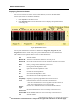


Table Of Contents
- WMTS Transceivers
- About Transceivers
- Programming Transceivers
- Displaying Transceiver Status
- User Warnings, Cautions, and Notes
- Ambulatory Transceiver (DT-4500)
- Operating Instructions
- Push Button Function and Use
- LED Indicators Function
- Cleaning
- Cleaning the Chassis
- Cleaning the Battery Compartment
- Cleaning the ECG Leadsets
- Use and Maintenance
- Transceiver Storage
- Attaching and Removing a Leadset from the Transcei...
- Internal Antenna
- Installing and Removing a Battery
- Warnings
- Cautions
- Instrument Transceiver (DT-7000, DT-7001)

WMTS TRANSCEIVERS
190 PatientNet Operator’s Manual, v1.04, 10001001-003, Revision B
All information contained herein is subject to the rights and restrictions on the title page.
Fig. 91. DT-4500 Controls and LED Indicators
Note: *The External Serial Device (I/O) Cable must be removed and the Connector
must be covered whenever the DT-4500 is connected to the patient.
Battery Compartment
Electrode Status Indicators
Remote Record button
Battery Low, RF, and I/O
Connector Link Status Indicators
Procedure Alarm Silence button
Procedure Alarm Silence
Status Indicator
Nurse Call button
Attendant Present / Procedure
Alarm Silence Unlock buttons
ECG Leadset and connector
cover
*External Serial Device (I/O)
Cable
ECG Leadset Connector
*External Serial Device (I/O)
Connector