
User's Manual
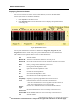


Table Of Contents
- WMTS Transceivers
- About Transceivers
- Programming Transceivers
- Displaying Transceiver Status
- User Warnings, Cautions, and Notes
- Ambulatory Transceiver (DT-4500)
- Operating Instructions
- Push Button Function and Use
- LED Indicators Function
- Cleaning
- Cleaning the Chassis
- Cleaning the Battery Compartment
- Cleaning the ECG Leadsets
- Use and Maintenance
- Transceiver Storage
- Attaching and Removing a Leadset from the Transcei...
- Internal Antenna
- Installing and Removing a Battery
- Warnings
- Cautions
- Instrument Transceiver (DT-7000, DT-7001)

WMTS TRANSCEIVERS
PatientNet Operator’s Manual, v1.04, 10001001-003, Revision B 185
All information contained herein is subject to the rights and restrictions on the title page.
Impedance Values
The DT-4500 Ambulatory Transceivers electrode impedance values, which are
displayed on the OpenNet Transceiver Status screen, indicate the quality of the signal
connection and are not the actual impedance values that are measured by the system.
The electrode impedance values range from 100 to 200 (optimal). The typical values
range between 180 and 200.
If the electrode’s impedance value is greater than the defined Quality Threshold value,
then its LED is illuminated. The DT-4500 stores the Quality Threshold value and uses
this value to determine whether or not the electrode LED should be illuminated when
the Attendant Present buttons are pressed. See Figure 91 on page 190 for details on the
DT-4500 Buttons and LED indicators.
Note: A Lead Off alarm will occur when an electrode’s impedance value drops to
150 (150 is the default Loose Lead Threshold value).
User Warnings, Cautions, and Notes
Before operating the WMTS transceivers, read and follow all warnings and cautions
presented in this section.
Warnings
1. Do not use the output of the DT-4500 as a synchronization source for car-
diac defibrillation. Delays in presentation of the R-Wave may be as much
as 40 milliseconds.
2. Do not monitor pacer patients with a 3 wire leadset when reliable pacer
detection is required. Pacer pulse detection can be erratic when only a
single vector is monitored. Always use a 5 wire leadset when reliable
pacer detection is required.
3. The DT-4500 is a type BF patient applied device. It is not suitable for
direct cardiac application, for use in the operating room, or during car-
diac surgery. Use in these environments could cause hazardous voltages
and currents being applied to the patient’s heart, resulting in cardiac
arrest.
4. Only authorized type BF devices can be plugged into the accessory con-
nector of the DT-4500 when it is applied to the patient. The accessory
connector must be kept covered when not in use with the supplied acces-
sory connector cover. Failure to follow these instructions could lead to
hazardous voltages and currents being applied to the patient resulting in
cardiac arrest.
5. Total submersion of the patient worn transceiver and/or patient leadset/
antenna may severely limit its transmission range causing loss of patient
monitoring. When subjecting the patient and transceiver to submersion,
he/she should be carefully monitored to ensure that there is no signal loss.
6. Use only VitalCom Power Supply Part Number 395005 with the DT-7000/
DT-7001.