
User's Manual Part 2

68 Mercury Reference Manual 05-4446A01, Rev. D
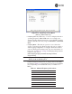
• RF Bandwidth—View/set the radio’s RF operating bandwidth.
Radios are factory-configured for either 1.75 MHz or 3.5
MHz maximum bandwidth. Determine the factory configu-
ration of a radio by viewing the “CONFIG” number on the
label at the bottom of the radio. 1.75 MHz units will have a
Configuration string starting with
HGA/R9N1, and 3.5 MHz
units will have a string starting with HGA/R9N3.
The bandwidth setting on this menu does not necessarily
have to match the configured bandwidth of the radio, but it is
limited by it. That is, you can set a 3.5 MHz radio to either
1.75 or 3.5, but you can only set a 1.75 MHz radio to 1.75.
Note that setting a 3.5 MHz bandwidth radio to operate at
1.75 MHz bandwidth will cause a slight degradation of inter-
ference rejection capability. Note that this parameter is
read-only when
Frequency Mode is set to Hopping w/Hand-offs.
[1.75MHz, 3.5MHz]
The Mercury 3650 can operate at 1.75 MHz, 3.5 MHz, 5
MHz, or 7 MHz bandwidth. The unit uses a digital filter so
that any unit can operate at any bandwidth.
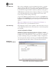
• Single Frequency Channel—The RF frequency that the inte-
grated radio will operate on when in single frequency
(non-hopping) mode. [
0 to 6 for 3.5-MHz, 0 to 13 for 1.75-MHz; 0].
• Frame Duration—Defines the over-the-air media access con-
trol framing. Note that this parameter is read-only when Fre-
quency Mode is set to Hopping w/Hand-offs. [5, 8, 10, or 20 msec;
20 msec]
• Hop Pattern—Selects a pre-defined series of channels that is
followed when hopping. Note that this parameter is read-only
when
Frequency Mode is set to Hopping w/Hand-offs.
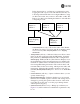
• Hop Pattern Offset—Inserts an offset into the hop pattern that
is synchronized with the GPS. For example, if the offset is 0,
the start of the pattern is aligned with the GPS timing. If the
offset is 3, then the fourth hop of the pattern is aligned with
the GPS timing. All of the APs that are part of a network
should use the same pattern and each one should have its own
offset.
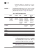
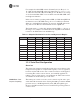
7 916.000000
8 917.800000
9 919.600000
10 921.400000
11 923.400000
12 925.200000
13 927.000000
Table 3-1. Channel/Frequency Allocations (Continued)
Channel 1.75 MHz B/W 3.5 MHz B/W