Installation Guide Infinity C™ DC to DC Power System Models 663 / 664 dc to dc Power Shelf 24v or 48V dc Output Service and Assistance - +1 877 546 3243 or +1 972 244 9288 © 2012 General Electric Company. All rights reserved. CC848921016 r02 December 2012 PE.TechSupport@ge.com http://www.ge.
663 / 664E Installation Guide Table of Contents Table of Contents ............................................................................................................................................................................ 2 Introduction ....................................................................................................................................................................................... 3 Reference Documents ...................................................
663 / 664E Installation Guide Introduction This manual is intended as a guide in assisting equipment understanding, installation, testing, and troubleshooting. For additional assistance contact Customer Service or access additional information on-line.
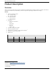
663 / 664E Installation Guide Product Description Overview Infinity C™ dc to dc power shelves convert and distribute available battery voltage to another dc voltage. This allows a single bank of batteries to provide battery reserve for equipment operating at a different dc voltage.
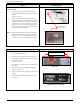
663 / 664E Installation Guide Configurations 6 CB, 10 GMT, 3 Converters 4 CB, 10 GMT, 4 Converters 6 CB, 4 Converters Converters Latch Status LEDs Converter Front View Converter retaining latch open CC848921016 r02 December 2012 Page 5
63 / 664E Installation Guide Installation Preparation Safety Read and follow all safety statements, warnings, and precautions in the Safety section of this manual and manuals of all other equipment before installing, maintaining or repairing the equipment. Product manuals contain additional safety statements, warnings, and precautions specific to the products.
663 / 664E Installation Guide Step 2 Ground Chassis Chassis Ground • Vertical or horizontal chassis ground cable landings are threaded holes 1/4-20 on 5/8 inch centers Torque to 240 in-lb • Chassis ground connections are available if customer standards require the power system to have an independent grounding connection.
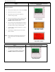
663 / 664E Installation Guide Step 4 • Run and terminate alarm cabling • Jumper settings are available for both Close on Alarm and Open on Alarm extensions • Verify alarm extensions with the Alarm Center • See Pulsar Edge Controller Family Product Manual for additional information Run and Terminate Alarm Cabling Front Connectorized Alarm Cable connection Step 5 Run & Term.
663 / 664E Installation Guide Step 6 Energize Power Plant Start up • Remove all converter modules from the power plant if previously installed • Insert a single converter and turn on the input breaker to this converter. This will apply input voltage to the controller and system load bus.
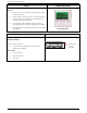
663 / 664E Installation Guide Step 8 System Verification and Alarm Extension Verification Using the Controller • Verify that the display screen is illuminated Green • Verify that no alarms are reported • Verify status of all converter modules are communicating properly • Verify all extended alarms with the Alarm Center. (see Pulsar Edge Controller Family Product Manual for alarm extension test) • Verify that the plant voltage displayed is within ± 0.
663 / 664E Installation Guide Safety Safety Statements Read and follow these statements and those in equipment manuals. • Do not install this equipment over combustible surfaces. • Follow all national and local rules and regulations when making field connections. • Compression Connectors • For installations in the U. S. or Canada, use Listed/Certified compression connectors to terminate Listed/Certified field-wire conductors where required.
663 / 664E Installation Guide Warning and Safety Symbols The symbols may sometimes be accompanied by some type of statement, e.g. “Hazardous voltage/energy inside. Risk of injury. This unit must be accessed only by qualified personnel.” Signal words as described below may also be used to indicate the level of hazard DANGER Indicates the presence of a hazard that will cause death or severe personal injury if the hazard is not avoided.
663 / 664E Installation Guide Precautions Read and follow these precautions and those in equipment manuals. • The equipment must be installed, serviced, and operated only by professional, skilled and qualified personnel who have the necessary knowledge and practical experience with electrical equipment and who understand the hazards that can arise when working on this type of equipment. • The equipment may be powered by multiple AC inputs.
663 / 664E Installation Guide Revision History Issue 2 Removed reference to rectifiers, rebrand, reformat Issue 1 Initial Release CC848921016 r02 December 2012 Page 14