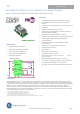
GE Data Sheet 20A Digital MicroDLynxTM: Non-Isolated DC-DC Power Modules 3Vdc –14.4Vdc input; 0.45Vdc to 5.5Vdc output; 20A Output Current Features RoHS Compliant Applications Compliant to RoHS EU Directive 2002/95/EC (Z versions) Compatible in a Pb-free or SnPb reflow environment (Z versions) Compliant to IPC-9592 (September 2008), Category 2, Class II DOSA based Wide Input voltage range (3Vdc-14.4Vdc) Output voltage programmable from 0.45Vdc to 5.
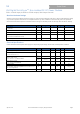
GE Data Sheet 20A Digital MicroDLynxTM: Non-Isolated DC-DC Power Modules 3Vdc –14.4Vdc input; 0.45Vdc to 5.5Vdc output; 20A Output Current Absolute Maximum Ratings Stresses in excess of the absolute maximum ratings can cause permanent damage to the device. These are absolute stress ratings only, functional operation of the device is not implied at these or any other conditions in excess of those given in the operations sections of the data sheet.
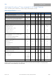
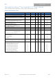
GE Data Sheet 20A Digital MicroDLynxTM: Non-Isolated DC-DC Power Modules 3Vdc –14.4Vdc input; 0.45Vdc to 5.5Vdc output; 20A Output Current Electrical Specifications (continued) Parameter Output Voltage Set-point (with 0.
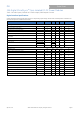
GE Data Sheet 20A Digital MicroDLynxTM: Non-Isolated DC-DC Power Modules 3Vdc –14.4Vdc input; 0.45Vdc to 5.5Vdc output; 20A Output Current Electrical Specifications (continued) Parameter Device Frequency Synchronization Symbol Min Typ Max Unit 600 kHz All Synchronization Frequency Range All High-Level Input Voltage All 425 Low-Level Input Voltage All VIL 0.
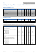
GE Data Sheet 20A Digital MicroDLynxTM: Non-Isolated DC-DC Power Modules 3Vdc –14.4Vdc input; 0.45Vdc to 5.5Vdc output; 20A Output Current Feature Specifications (cont.) Parameter Device Symbol Min Typ Max Units All Tdelay ― 1.2 ― msec All Tdelay ― 0.8 ― msec All Trise ― 2.7 ― msec 3.
GE Data Sheet 20A Digital MicroDLynxTM: Non-Isolated DC-DC Power Modules 3Vdc –14.4Vdc input; 0.45Vdc to 5.5Vdc output; 20A Output Current Digital Interface Specifications Unless otherwise indicated, specifications apply over all operating input voltage, resistive load, and temperature conditions. See Feature Descriptions for additional information. Parameter Conditions Symbol Min Input High Voltage (CLK, DATA) VIH 2.
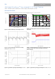
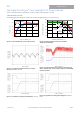
GE Data Sheet 20A Digital MicroDLynxTM: Non-Isolated DC-DC Power Modules 3Vdc –14.4Vdc input; 0.45Vdc to 5.5Vdc output; 20A Output Current Characteristic Curves The following figures provide typical characteristics for the 20A Digital MicroDLynxTM at 0.6Vo and 25oC. 22 90 85 18 OUTPUT CURRENT, Io (A) EFFICIENCY, (%) 80 Vin=3.3V 75 70 Vin=14V Vin=12V 65 60 55 50 0 5 10 15 NC 1m/s 10 (200LFM) 6 1.
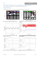
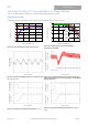
GE Data Sheet 20A Digital MicroDLynxTM: Non-Isolated DC-DC Power Modules 3Vdc –14.4Vdc input; 0.45Vdc to 5.5Vdc output; 20A Output Current Characteristic Curves The following figures provide typical characteristics for the 20A Digital MicroDLynxTM at 1.2Vo and 25oC. 22 95 90 18 85 EFFICIENCY, (%) 80 OUTPUT CURRENT, Io (A) Vin=3.3V Vin=14V 75 Vin=12V 70 65 60 55 50 0 5 10 15 NC 14 0.5m/s (100LFM) 10 1.
GE Data Sheet 20A Digital MicroDLynxTM: Non-Isolated DC-DC Power Modules 3Vdc –14.4Vdc input; 0.45Vdc to 5.5Vdc output; 20A Output Current Characteristic Curves The following figures provide typical characteristics for the 20A Digital MicroDLynxTM at 1.8Vo and 25oC. 22 95 18 90 85 OUTPUT CURRENT, Io (A) EFFICIENCY, (%) Vin=3.3V Vin=14V Vin=12V 80 75 70 0.5m/s (100LFM) 10 5 10 15 20 1.
GE Data Sheet 20A Digital MicroDLynxTM: Non-Isolated DC-DC Power Modules 3Vdc –14.4Vdc input; 0.45Vdc to 5.5Vdc output; 20A Output Current Characteristic Curves The following figures provide typical characteristics for the 20A Digital MicroDLynxTM at 2.5Vo and 25oC. 22 100 Vin=12V 95 OUTPUT CURRENT, Io (A) 18 EFFICIENCY, (%) 90 Vin=4.5V 85 Vin=14V 80 75 70 NC 14 10 1.
GE Data Sheet 20A Digital MicroDLynxTM: Non-Isolated DC-DC Power Modules 3Vdc –14.4Vdc input; 0.45Vdc to 5.5Vdc output; 20A Output Current Characteristic Curves The following figures provide typical characteristics for the 20A Digital MicroDLynxTM at 3.3Vo and 25oC. 22 100 Vin=12V 95 OUTPUT CURRENT, Io (A) 18 EFFICIENCY, (%) 90 Vin=14V 85 Vin=4.5V 80 75 70 0.5m/s (100LFM) 1m/s (200LFM) 1.
GE Data Sheet 20A Digital MicroDLynxTM: Non-Isolated DC-DC Power Modules 3Vdc –14.4Vdc input; 0.45Vdc to 5.5Vdc output; 20A Output Current Characteristic Curves The following figures provide typical characteristics for the 20A Digital MicroDLynxTM at 5Vo and 25oC. 100 22 Vin=12V 95 OUTPUT CURRENT, Io (A) 18 EFFICIENCY, (%) 90 Vin=7V Vin=14V 85 80 75 70 NC 0.5m/s (100LFM) 1m/s (200LFM) 1.
GE Data Sheet 20A Digital MicroDLynxTM: Non-Isolated DC-DC Power Modules 3Vdc –14.4Vdc input; 0.45Vdc to 5.5Vdc output; 20A Output Current 70 Input Filtering 60 The 20A Digital MicroDLynxTM module should be connected to a low ac-impedance source. A highly inductive source can affect the stability of the module. An input capacitance must be placed directly adjacent to the input pin of the module, to minimize input ripple voltage and ensure module stability.
GE Data Sheet 20A Digital MicroDLynxTM: Non-Isolated DC-DC Power Modules 3Vdc –14.4Vdc input; 0.45Vdc to 5.5Vdc output; 20A Output Current Analog Feature Descriptions Digital On/Off Remote On/Off Please see the Digital Feature Descriptions section. The module can be turned ON and OFF either by using the ON/OFF pin (Analog interface) or through the PMBus interface (Digital).
GE Data Sheet 20A Digital MicroDLynxTM: Non-Isolated DC-DC Power Modules 3Vdc –14.4Vdc input; 0.45Vdc to 5.5Vdc output; 20A Output Current Table 1 the minimum of 3V. . 16 VO, set (V) 0.6 0.9 1.0 1.2 1.5 1.8 2.5 3.3 5.0 Input Voltage (v) 14 12 Upper 10 8 6 4 Lower 2 0 0.5 1 1.5 2 2.5 3 3.5 4 4.5 5 5.5 Rtrim (KΩ) Open 40 30 20 13.33 10 6.316 4.444 2.727 6 Output Voltage (V) Figure 41. Output Voltage vs.
GE Data Sheet 20A Digital MicroDLynxTM: Non-Isolated DC-DC Power Modules 3Vdc –14.4Vdc input; 0.45Vdc to 5.5Vdc output; 20A Output Current Please see the Digital Feature Descriptions section. continue operation without interruption as the response to this fault (see the description of the PMBus command VOUT_UV_FAULT_RESPONSE for additional information).
GE Data Sheet 20A Digital MicroDLynxTM: Non-Isolated DC-DC Power Modules 3Vdc –14.4Vdc input; 0.45Vdc to 5.5Vdc output; 20A Output Current Synchronization The module switching frequency can be synchronized to a signal with an external frequency within a specified range. Synchronization can be done by using the external signal applied to the SYNC pin of the module as shown in Fig. 45, with the converter being synchronized by the rising edge of the external signal.
GE Data Sheet 20A Digital MicroDLynxTM: Non-Isolated DC-DC Power Modules 3Vdc –14.4Vdc input; 0.45Vdc to 5.5Vdc output; 20A Output Current Tunable LoopTM The module has a feature that optimizes transient response of the module called Tunable LoopTM. External capacitors are usually added to the output of the module for two reasons: to reduce output ripple and noise (see Figure 38) and to reduce output voltage deviations from the steady-state value in the presence of dynamic load current changes.
GE Data Sheet 20A Digital MicroDLynxTM: Non-Isolated DC-DC Power Modules 3Vdc –14.4Vdc input; 0.45Vdc to 5.5Vdc output; 20A Output Current Digital Feature Descriptions either address resistor value is outside the range specified in Table 4, the module will respond to address 127. PMBus Interface Capability Table 4 The 20A Digital MicroDLynxTM power modules have a PMBus interface that supports both communication and control. The PMBus Power Management Protocol Specification can be obtained from www.
GE Data Sheet 20A Digital MicroDLynxTM: Non-Isolated DC-DC Power Modules 3Vdc –14.4Vdc input; 0.45Vdc to 5.5Vdc output; 20A Output Current PU: Sets the default to either operate any time input power is present or for the ON/OFF to be controlled by the analog ON/OFF input and the PMBus OPERATION command. This bit is used together with the CP, CMD and ON bits to determine startup.
GE Data Sheet 20A Digital MicroDLynxTM: Non-Isolated DC-DC Power Modules 3Vdc –14.4Vdc input; 0.45Vdc to 5.5Vdc output; 20A Output Current Output Voltage Margining Using the PMBus The module can also have its output voltage margined via PMBus commands. The command VOUT_MARGIN_HIGH sets the margin high voltage, while the command VOUT_MARGIN_LOW sets the margin low voltage. Both the VOUT_MARGIN_HIGH and VOUT_MARGIN_LOW commands use the “Linear” mode with the exponent fixed at –10 (decimal).
GE Data Sheet 20A Digital MicroDLynxTM: Non-Isolated DC-DC Power Modules 3Vdc –14.4Vdc input; 0.45Vdc to 5.5Vdc output; 20A Output Current PMBus Adjustable Input Undervoltage Lockout The module allows adjustment of the input under voltage lockout and hysteresis. The command VIN_ON allows setting the input voltage turn on threshold, while the VIN_OFF command sets the input voltage turn off threshold. For the VIN_ON command, possible values are 2.75V, and 3V to 14V in 0.5V steps.
GE Data Sheet 20A Digital MicroDLynxTM: Non-Isolated DC-DC Power Modules 3Vdc –14.4Vdc input; 0.45Vdc to 5.5Vdc output; 20A Output Current TIND, it may be approximated by an estimate of the module temperature. Measuring Output Voltage Using the PMBus The module can provide output voltage information using the READ_VOUT command. The command returns two bytes of data all representing the mantissa while the exponent is fixed at -10 (decimal).
GE Data Sheet 20A Digital MicroDLynxTM: Non-Isolated DC-DC Power Modules 3Vdc –14.4Vdc input; 0.45Vdc to 5.5Vdc output; 20A Output Current STATUS_IOUT : Returns one byte of information relating to the status of the module’s output voltage related faults.
GE Data Sheet 20A Digital MicroDLynxTM: Non-Isolated DC-DC Power Modules 3Vdc –14.4Vdc input; 0.45Vdc to 5.5Vdc output; 20A Output Current Summary of Supported PMBus Commands Please refer to the PMBus 1.1 specification for more details of these commands. Table 6 Hex Code Command Non-Volatile Memory Storage Brief Description Turn Module on or off.
GE Data Sheet 20A Digital MicroDLynxTM: Non-Isolated DC-DC Power Modules 3Vdc –14.4Vdc input; 0.45Vdc to 5.
GE Data Sheet 20A Digital MicroDLynxTM: Non-Isolated DC-DC Power Modules 3Vdc –14.4Vdc input; 0.45Vdc to 5.
GE Data Sheet 20A Digital MicroDLynxTM: Non-Isolated DC-DC Power Modules 3Vdc –14.4Vdc input; 0.45Vdc to 5.
GE Data Sheet 20A Digital MicroDLynxTM: Non-Isolated DC-DC Power Modules 3Vdc –14.4Vdc input; 0.45Vdc to 5.
GE Data Sheet 20A Digital MicroDLynxTM: Non-Isolated DC-DC Power Modules 3Vdc –14.4Vdc input; 0.45Vdc to 5.
GE Data Sheet 20A Digital MicroDLynxTM: Non-Isolated DC-DC Power Modules 3Vdc –14.4Vdc input; 0.45Vdc to 5.
GE Data Sheet 20A Digital MicroDLynxTM: Non-Isolated DC-DC Power Modules 3Vdc –14.4Vdc input; 0.45Vdc to 5.5Vdc output; 20A Output Current Table 6 (continued) Hex Code D6 D7 Command VIN_CAL_OFFSET VIN_CAL_GAIN April 24, 2013 Brief Description Non-Volatile Memory Storage Applies an offset correction to the READ_VIN command results to calibrate out offset errors in module measurements of the input voltage (between -2V and +1.
GE Data Sheet 20A Digital MicroDLynxTM: Non-Isolated DC-DC Power Modules 3Vdc –14.4Vdc input; 0.45Vdc to 5.5Vdc output; 20A Output Current Thermal Considerations Power modules operate in a variety of thermal environments; however, sufficient cooling should always be provided to help ensure reliable operation. Considerations include ambient temperature, airflow, module power dissipation, and the need for increased reliability.
GE Data Sheet 20A Digital MicroDLynxTM: Non-Isolated DC-DC Power Modules 3Vdc –14.4Vdc input; 0.45Vdc to 5.5Vdc output; 20A Output Current Shock and Vibration The ruggedized (-D version) of the modules are designed to withstand elevated levels of shock and vibration to be able to operate in harsh environments.
GE Data Sheet 20A Digital MicroDLynxTM: Non-Isolated DC-DC Power Modules 3Vdc –14.4Vdc input; 0.45Vdc to 5.5Vdc output; 20A Output Current Example Application Circuit Requirements: Vin: 12V Vout: 1.8V Iout: 15A max., worst case load transient is from 10A to 15A Vout: 1.5% of Vout (27mV) for worst case load transient Vin, ripple 1.
GE Data Sheet 20A Digital MicroDLynxTM: Non-Isolated DC-DC Power Modules 3Vdc –14.4Vdc input; 0.45Vdc to 5.5Vdc output; 20A Output Current Mechanical Outline Dimensions are in millimeters and (inches). Tolerances: x.x mm 0.5 mm (x.xx in. 0.02 in.) [unless otherwise indicated] x.xx mm 0.25 mm (x.xxx in 0.010 in.
GE Data Sheet 20A Digital MicroDLynxTM: Non-Isolated DC-DC Power Modules 3Vdc –14.4Vdc input; 0.45Vdc to 5.5Vdc output; 20A Output Current Recommended Pad Layout Dimensions are in millimeters and (inches). Tolerances: x.x mm 0.5 mm (x.xx in. 0.02 in.) [unless otherwise indicated] x.xx mm 0.25 mm (x.xxx in 0.010 in.
GE Data Sheet 20A Digital MicroDLynxTM: Non-Isolated DC-DC Power Modules 3Vdc –14.4Vdc input; 0.45Vdc to 5.5Vdc output; 20A Output Current Packaging Details The 12V Digital MicroDLynxTM 20A modules are supplied in tape & reel as standard. Modules are shipped in quantities of 200 modules per reel. All Dimensions are in millimeters and (in inches). Reel Dimensions: Outside Dimensions: 330.2 mm (13.00) Inside Dimensions: 177.8 mm (7.00”) Tape Width: 44.00 mm (1.
GE Data Sheet 20A Digital MicroDLynxTM: Non-Isolated DC-DC Power Modules 3Vdc –14.4Vdc input; 0.45Vdc to 5.5Vdc output; 20A Output Current Pick and Place The 20A Digital MicroDLynxTM modules use an open frame construction and are designed for a fully automated assembly process. The modules are fitted with a label designed to provide a large surface area for pick and place operations.
GE Data Sheet 20A Digital MicroDLynxTM: Non-Isolated DC-DC Power Modules 3Vdc –14.4Vdc input; 0.45Vdc to 5.5Vdc output; 20A Output Current Ordering Information Please contact your GE Sales Representative for pricing, availability and optional features. Table 9. Device Codes Device Code Input Voltage Range Output Voltage Output Current On/Off Logic Sequencing Comcodes UDT020A0X3-SRZ 3 – 14.4Vdc 0.45 – 5.5Vdc 20A Negative Yes CC109159728 UDT020A0X3-SRDZ 3 – 14.4Vdc 0.45 – 5.