
Owner's manual

GE
Datasheet
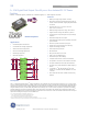
2 × 12A Digital Dual MicroDlynx
TM
: Non-Isolated DC-DC Power Modules
4.5Vdc –14.4Vdc input; 0.51Vdc to 5.5Vdc output; 2 × 12AOutput Current
February 14, 2014 ©2014 General Electric Corporation. All rights reserved. Page 6
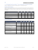
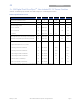
Digital Interface Specifications
Unless otherwise indicated, specifications apply over all operating input voltage, resistive load, and temperature conditions. See
Feature Descriptions for additional information.
Parameter Conditions Symbol Min Typ Max Unit
PMBus Signal Interface Characteristics
Input High Voltage (CLK, DATA) VIH 2.1 V
Input Low Voltage (CLK, DATA) VIL 0.8 V
Input high level current (CLK, DATA) I
IH
-10 10 A
Input low level current (CLK, DATA) I
IL
-10 10 mA
Output Low Voltage (CLK, DATA, SMBALERT#) I
OUT
=2mA VOL 0.4? V
Output high level open drain leakage current (DATA,
SMBALERT#)
V
OUT
=3.6V I
OH
0 10 A
Pin capacitance C
O
0 1 pF
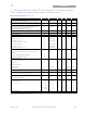
PMBus Operating frequency range Slave Mode FPMB 10 400 kHz
Data hold time
Receive Mode
Transmit Mode
tHD:DAT
0
300
ns
Data setup time
tSU:DAT
250 ns
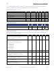
Measurement System Characteristics
Output current measurement range
I
RNG
0 18 A
Output current measurement gain accuracy (at 25°C)
I
ACC
±1 A
V
OUT
measurement range
V
OUT(rng)
0.5 5.8 V
V
OUT
measurement accuracy
-2 2 %