
Owner's manual

GE
Datasheet
2 × 12A Digital Dual MicroDlynx
TM
: Non-Isolated DC-DC Power Modules
4.5Vdc –14.4Vdc input; 0.51Vdc to 5.5Vdc output; 2 × 12A Output Current
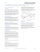
February 14, 2014 ©2014 General Electric Corporation. All rights reserved. Page 33
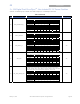
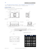
Recommended Pad Layout
Dimensions are in millimeters and (inches).
Tolerances: x.x mm
±
0.5 mm (x.xx in.
±
0.02 in.) [unless otherwise indicated]
x.xx mm
±
0.25 mm (x.xxx in
±
0.010 in.)
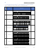
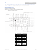
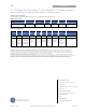
PIN FUNCTION PIN FUNCTION
1 VSNS1 15 ADDR1
2 VOUT1 16 TRIM1
3 PGND 17 Sig_GND
4 VOUT2 18 TRIM2
5 VSNS2 19 SYNC
6 SMBALERT# 20 PGND
7 DATA 21 PGND
8 CLK 22 PGND
9 ENABLE1 23 PGND
10 ENABLE2 24 PGND
11 VIN 25 PGND
12 PGND 26 PGND
13 VIN 27 PGOOD2
14 ADDRO 28 PGOOD1