
Owner's manual

GE
Datasheet
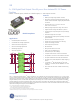
2 × 12A Digital Dual MicroDlynx
TM
: Non-Isolated DC-DC Power Modules
4.5Vdc –14.4Vdc input; 0.51Vdc to 5.5Vdc output; 2 × 12A Output Current
February 14, 2014 ©2014 General Electric Corporation. All rights reserved. Page 2
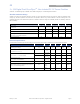
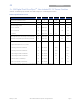
Absolute Maximum Ratings
Stresses in excess of the absolute maximum ratings can cause permanent damage to the device. These are absolute stress
ratings only, functional operation of the device is not implied at these or any other conditions in excess of those given in the
operations sections of the data sheet. Exposure to absolute maximum ratings for extended periods can adversely affect the
device reliability.
Parameter Device Symbol Min Max Unit
Input Voltage All V
IN1
and
V
IN2
-0.3 15 V
Continuous
VS+1, VS+2, SMBALERT# All -0.3 7 V
CLK, DATA, SYNC, All -0.3 3.6 V
Operating Ambient Temperature All T
A
-40 85 °C
(see Thermal Considerations section)
Storage Temperature All T
stg
-55 125 °C
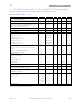
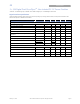
Electrical Specifications
Unless otherwise indicated, specifications apply over all operating input voltage, resistive load, and temperature conditions.
Parameter Device Symbol Min Typ Max Unit
Operating Input Voltage All
V
IN1
and
V
IN2
4.5
⎯
14.4 Vdc
Maximum Input Current All
I
IN1,max &
I
IN2,max
23 Adc
(V
IN
=3V to 14.4V, I
O
=I
O, max
)
Input No Load Current
(V
IN
= 12Vdc, I
O
= 0, module enabled)
V
O,set
= 0.6 Vdc
I
IN1,No load
&
I
IN2,No load
72 mA
V
O,set
= 5.5Vdc
I
IN,1No load
&
I
IN2,No load
210 mA
Input Stand-by Current
(V
IN
= 12Vdc, module disabled)
All
I
IN1,stand-by
&
I
IN2,stand-by
14 mA
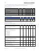
Inrush Transient All I
1
2
t & I
2
2
t 1 A
2
s
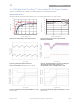
Input Reflected Ripple Current, peak-to-peak
(5Hz to 20MHz, 1H source impedance; V
IN
=4.5 to 14V
,
I
O
= I
Omax
; See Test Configurations)
All
Both
Inputs
25 mAp-p
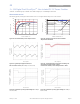
Input Ripple Rejection (120Hz) All
Both
Inputs
-68 dB